How-To: GT2B --> Badwolf v2

lox897 said:
Whitepony, what do you mean by one side goes on shield/ground and one on antenna? So the antenna cable is on left and shield/ground (the silvery bit?) on right?

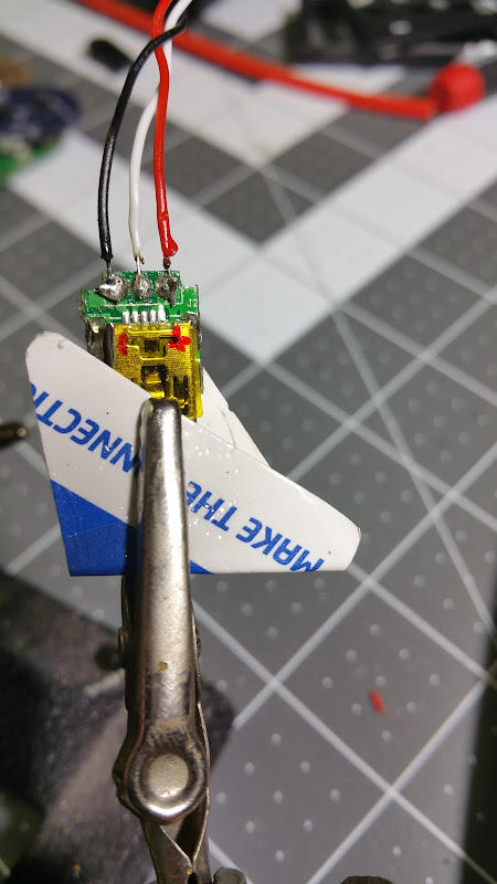
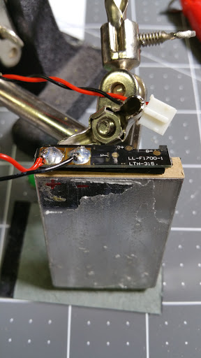
looking at my picture: if by left you mean top (or middle, smallest soldering spot) and by right you mean bottom (or outmost soldering spot) then yea, thats what I mean. for the short distances of transmitter/receiver it probably doesnt really matter if you have ANY antenna.

the antenna is a coax type antenna, so it has an inner core, surrounded by an inner insulator, surrounded by an outer shield, surrounded by outer insulation.
 
nice addition whitepony - thanks!

I got a PM with a good question:
Where to I solder and connect the usb wires and the battery wires to? I can't find the info in the post. Thanks.

Seems like if it's not clear we should add it here so others can see/learn. Don't mind the PM of course, but if i didn't clearly show it then let's re-discuss and sort it out.

USB wires:
20150815_191856.jpg

re-using the wires from the handle, the 3 wires to the USB Mini B charging port

20150815_201031.jpg

A bit of a closeup of the battery and charging ports. Note that the USB charging port does use all 3 wires, but since i had to mangle it a bit when desoldering the port, i put the white wire in the middle to the bottom side (more room to work at the time as well). So top has black and red, with the middle white connected on the bottom. You can also see the notched out part of the throttle assembly to clear the bind button and throttle adjustment. To keep it straight (what does what), i used the label from under the top cover to help keep them ID'd.

So USB wires on the top should be clear. Note i did connect the center white wire, but several have not and it didn't seem to be needed. I had difficulty finding how the wires connected as well, and saw in one of the pics from Badwolf v1 (angular version) he used all 3, so i did the same.

Then in the bottom picture you can see the red and black connected (black on top, red on bottom.). I had trouble soldering the white in-between the red/black, so i connected it to the middle on the bottom. Then lots of hot glue to keep everything in place.

Next up - battery.

Battery is pretty easy. I purposefully did not damage the plug so i could strip the wire and solder it directly to the + and - on the lipo. Then just plug it into the PCB like original.
Battery steps:
20150815_170836.jpg

Pry/peel off the plastic and cover around the battery. I immediately made sure to label + and - , just to be extra sure i dont mix them up.

20150815_171138.jpg

Test fit in other half of enclosure.

20150815_171901.jpg

A bead of solder on the + and - terminals on the battery, notice i kept the connector for the battery to connect to the PCB. Instead of hard wiring/soldering it later i could replace it easily.

20150815_172517.jpg
20150815_174210_001.jpg

Some electrical tape around the perimeter then gorilla taped it up.

HTH! GL!
 
sl33py said:
20150815_184302.jpg

You can see how much i cut away to give full throttle range.


about his thing - I kept thinking about this for a while and after testing I would like to add that the last 10°ish dont do anything anymore. its the same for full throttle as for full braking - youll arrive at 100% just about 10° before you cant pull/push the trigger any further because its stopped by its own mechanic. thats why that last bit doesnt really change anything anymore and you dont have to cut out a part of the enclosure.

I aligned my trigger so that it would hit max for full throttle just when its about to enter the enclosure like you did - mostly because it feels nice. :)
 
Hello, I have some questions regarding the USB port and the battery connections. I have a 2015 version 1.0 GT2B PCB and it would seem slightly different to the one in the pictures.
My connector plugs on the CH3 PCB board are soldered firmly in place - I can't take them off as in the picture below.
So I'm assuming that I keep everything connected as it is on the little CH3 PCB board and the main PCB board and then simply run 3 wires from the mini USB jack to the PCB pins where the USB jack came from originally?

file.php


It also means that I have to solder the battery in situ as the plug going to the tiny CH3 PCB board is also soldered solid.

Thanks.
 
Back
Top