Homemade Battery Packs

Typically, when they test cycle life, it is an automatic constant charge-discharge-charge-discharge cycle with minimal time setting at full voltage.
So, time setting at 4.20V would, likely, not have been considered as a factor in determining cycle life.

Time spent at higher voltages in "hot" climates is additionally and progressively damaging! - (for many Lithium battery types)
Limiting time at higher (4.20V) charged state in >~80ºF environment can additionally limit the severe additional deterioration.
Charging in a cooler location and using-reducing cell voltage below 4.10V before battery temperature rises is promoted to effectively reduce hot battery environment damage.
(~75ºF is considered optimal battery temperature - charging and discharging)
 
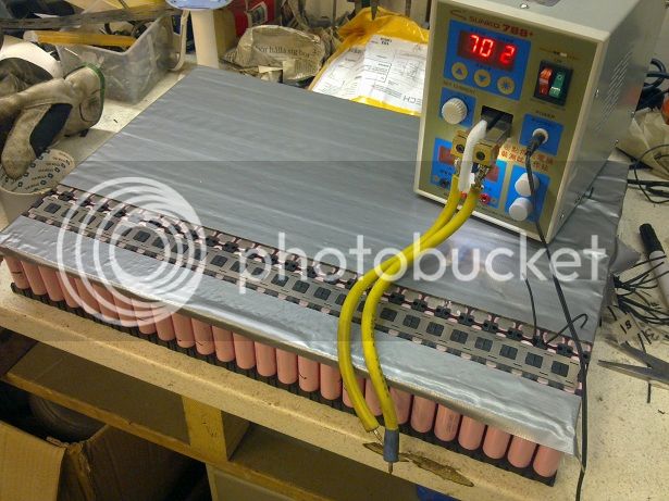
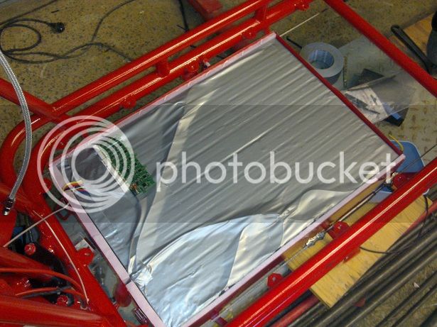
Here is my 13s9p pack. I blame DrkAngel for this, if he hadn't of been so helpful, I wouldn't have bothered to build one. Left half was built first, then a month later the right half was added when a friend dumped 20 laptop batteries on me.

True capacity is estimated at ~17ah. I try to keep max draw at 1C and peak at 1.5C, however, I've read various things about 'ideal' max draw should be 0.5 to 1C and peak should be 1C, due to lack of data, I will just see how it goes and learn.
 
As proposed-championed earlier,
It seems C rate is more directly related to actual capacity vs original rated capacity.

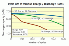
C rate is a major and progressive factor in battery deterioration!

cycle life and rate.gif
Deterioration to 80% of original capacity:
3C produces < 50 cycles
2C produces ~ 250 cycles
1C produces ~ 500 cycles
High C rate discharges (and charges) are progressively damaging and as actual capacity declines, deterioration accelerates rapidly!

My recommendation of limiting charges and discharges to ≤ .5C (1C surges) based on actual Capacity, is designed to extend battery toward optimal lifespan with reasonable battery size.
 
I keep coming back to this thread and check out the cost effective battery builds. Alot of nice info in it aswell.
Reading this recent discussion about battery aging, I am thinking I went over the top with babying the batteries in my cargobike.

It is a 18s26p configuration out of D1 cells. Basically an older low discharge high capacity cell at 3000mAh if charged to 4,35V.

Do you guys know if a lowered chargestop from 4,35V to say 4,2V has the same effect on these cells compared to a 4,2V to 4,1V chargestop on "regular" cells?
I have been riding my cargobike for close to 2700km since it was completed around mid july, and if all goes as planned I will use it more next summer.
This has resulted in something like ~35 chargecycles and only one was from an "empty state". I have been charging to 4,1V most of the time. Charging with ~18A (could lower this in most cases as there seldom is a hurry)
Most of the charges have been made when there was 30% or more capacity left. (Real wh capacity, tested with the single deep cycle for reference)

Discharging during riding is limited to 35A "98%" of the time. I occationally did some testing at up to 50A.
But almost all riding happens between 8A and 17A. Sometimes a hill that pulls 20-30A.
That would mean (if I put the occational 50A testing aside) that the cells see up to 0,5C peak and most often 0,2C-0,3C.

Can I improve something about my usage to prevent aging of these cells? Optimal charging speed? Im fearing time is aging them more than usage.

The cells will be stored at ~5-10C this winter.

VLJ46_zpslqntvrjk.jpg

VLJ62_zpsy0whzv6p.jpg
 
Since you seem to ride occasionally, (weekly?), not charging till night before ride should help prolong life.

While, for your cells, I've never seen a determination as to peak charge voltage affecting cycle life ... couldn't hurt and to limit charge/discharge cycles to the central capacity region will likely help.
 
Hey guys I have a question on welding tabs using those cheap ebay china welding machine boxes.

if you weld 1 tab to a battery, and it welds, then afterwards, can you weld a second tab on top of the first tab? Will the second tab stick on top of the first tab?

Or.. are you supposed to put both tabs on top of each other, then weld simultaneously together onto the battery top?
 
Full length strips are preferable for running cells in parallel.
Tabs for running in series.

But, welding a tab onto a tab should be no problem. - same as welding to cell.
(1 tab at a time)
 
about cycle life when charging lower as 4,2V per cell i have an article:

http://batteryuniversity.com/learn/article/how_to_prolong_lithium_based_batteries
it is about lipos, but it says "lithium based batteries". there are other interestnig articles as well on the page..

i also know of another test where cylce life was over 3times higher (before 80% dod) when only charging to 4,1V, but i could not find the link.. do not discharge below 3V should also lower stress.
 
I have problems with any "standard" DOD (Depth Of Discharge) for Lithium cells.

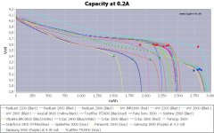
1st "empty", IMO, should be held as the point before the discharge curve "falls off the cliff" ... when discharged at minimal discharge rate.
As should be obvious to all, differing technologies indicate differing optimal discharge points at minimal, nearly static, discharge rates.

Capacity-0.2A.jpg
This collection displays 3 distinct static voltages at optimal.
3.60V
3.40V
and
3.20V

2nd This "optimal" DOD point shifts-drops a variable amount, dependent on discharge rate!
EG With laptop cells of a static cliff point of ~3.60V

file.php

At .2C discharge cliff point is ~3.60V
At .5C discharge cliff point is ~3.50V
At 1C discharge cliff point is ~3.30V
At 2C discharge cliff point is ~3.10V

RC Lipo packs sag similarly relative to their discharge capabilities, might sag to 3.10V but, at a 10C discharge rate.

Capacity Mapping helps determine optimal capacity ... charge discharge voltages.
Rather than running an actual discharge test, this "map" was built by carefully measuring the manufacturers discharge chart.
(Compare to discharge test for same Sanyo cell)

file.php

(Oops! 3.50V line should be labeled 3.55V ... 3.50V would touch and ~fill empty space )
This, hopefully" illustrates the minimal residual-available capacity after the "cliff point" highlighted in most discharge graphs.

Best way to determine your maximum DOD?
1st - Determine your optimal minimum voltage EG 3.60V
2nd - With battery near this voltage, run eBike at "normal" for a moderate time and monitor actual battery voltage.
Note and mark this typical use voltage as your "in use DOD".
Be aware that lighter or heavier use can vary this DOD voltage drastically
Alternately
With battery near your determined cliff point, run at various throttle for moderate periods (but not long enough to drain battery below cliff point).
Release throttle for a few seconds and note recovered voltage, should be slightly below static cliff point.
Compare at various throttle use and get a feel for when quick throttle check indicates optimal DOD.
Note and use as your quick check maximum DOD = empty indicator.

Oh ... I recommend a mounted volt meter to monitor battery!
With my 7s, I can combine a 8 wire ethernet cable to 1-8s VMA (Volt Meter Alarm) to monitor cell level voltages at the bars, or Cell-Log etc.
 
Friday, my buddy dropped off 30# of too-be-recycled laptop battery packs. I have spent a couple days breaking them open and charging them up.

However, I have found a few packs with red Sanyo UR18650fm m46a batteries. WHen charging these, I've had two doubles get 180F+ hot when charging. This is unusual for me, as Ive broken open over a hundred packs and this kind of failure hadn't happened before. Obviously, something went wrong in these, the question is this:
When you find a hot-to-charge double, do you throw out the others in the pack because they are from the same batch and may fail as well?

If it were just me, I'd say yes.
 
I've run into a batch of similar.
Sanyo that accordion nicely.
file.php

An unreasonably large percentage of these had at least 1 pair of overheating cells.
I gleaned a pitiful 84 decent usable cells from hundreds from identical brand and model packs. (Old model Gateway? been many years, not sure if remember correctly)
I would go further and not use any of the same packaged cells.
If too many to toss ... segregate and test very carefully and stringently.
 
What do you guys think about those eBay hobby welders from China? For $139-200 . Are they reliable and will the electrodes on those things last a long time or they need to be replaced often?
 
Well, I think what makes the Sanyo UR18650fm especially dangerous is that they were cool to the touch until the cells got over 4.xx and then I heard a pop and within a minute one pair was hotter than 180F. That unpredictable fail mode is good enough to pass simple tests then fail suddenly. What if it had happened on a road trip while recharging? Ugly.

So with your input, DrkAngel, I'm now putting down a ban on any Sanyo UR18650fm being in my main pack. Period.
 
Decided to test up a few hundred Sanyo cells
Damn! Could not find my modded S-150-5 MeanWell ...
Likely someone "borrowed" it without asking.

Anyhow, gave me a chance to test mods on a MeanWell S-320-5
S-240-x and S-320-x have very limited modability.
Swapped R48 resistor (pulled 1k and replaced with 2k) and succesfully shifted voltage range from 4.36V - 6.20V to 3.82V - 4.58V for 1s 4.2V ~65A+ charging.
5k or some in between ohm resistor or pot could likely shift to LiFe range? - Not tested.
MeanWell Mods documented on ESWiki - MeanWell.
 
Hey guys. I posted about my proposed build back in May, and got very sidetracked and never started on it.

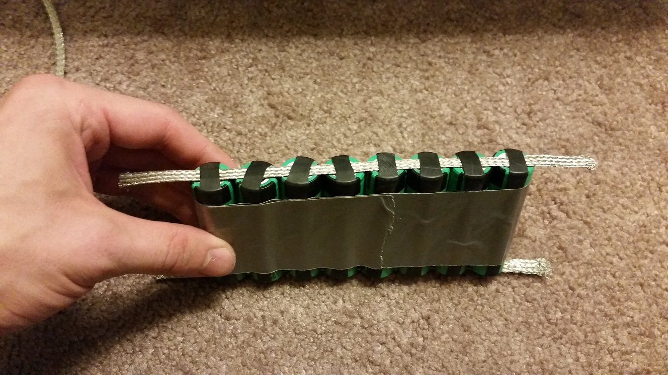
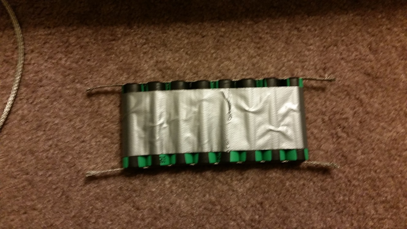
Well, I've finally started. I put together my first parallel group and... well, I'm questioning my whole design altogether. I'm not sure if there is enough compressive force from the rubber bands to maintain a good connection with my tinned copper.

My question is: is there any simple way for me to test this parallel group before I go on, to make sure all batteries have good contact with the rails? I don't have the equipment to do any kind of capacity testing, unfortunately.

This is what it looks like:
ByUADtb.jpg

KnF52Qa.jpg


FYI I'm making a 13s8p pack. Any advice appreciated, thanks!

(And yeah, definitely wishing I had gone with solder tabs at this point. Also, I do not have access to a spot welder.)
 
I don't believe there to be any reliable way to conclusively test. ... ?
I'm afraid the contacts to be unreliable and temperamental.

If determined to test or build with this method ...
Might work with insert (short nib of 12ga solid copper?), coated with conductive grease, inserted between contacts and braid?
 
DrkAngel said:
I don't believe there to be any reliable way to conclusively test. ... ?
I'm afraid the contacts to be unreliable and temperamental.

If determined to test or build with this method ...
Might work with insert (short nib of 12ga solid copper?), coated with conductive grease, inserted between contacts and braid?

Hey DrkAngel - I like your idea, I think I do just need some kind of bridging material like you described. The batteries have a protrusion the positive end, and that end seems fine, but the negative is slightly concave with the green outer wrapping and that is the side I'm concerned about - so I think this would solve that. I'll see about finding some conductive grease (already have copper). Thanks again, I'll let you know how it goes.

Also I definitely am not committed to this build, open to other ideas, but I don't want to solder on my batteries (I don't trust I will be able to do it without damaging the batteries) and as I mentioned, I do not have a spot welder to use.
 
ASK1 said:
DrkAngel said:
I don't believe there to be any reliable way to conclusively test. ... ?
I'm afraid the contacts to be unreliable and temperamental.

If determined to test or build with this method ...
Might work with insert (short nib of 12ga solid copper?), coated with conductive grease, inserted between contacts and braid?

Hey DrkAngel - I like your idea, I think I do just need some kind of bridging material like you described. The batteries have a protrusion the positive end, and that end seems fine, but the negative is slightly concave with the green outer wrapping and that is the side I'm concerned about - so I think this would solve that. I'll see about finding some conductive grease (already have copper). Thanks again, I'll let you know how it goes.

Also I definitely am not committed to this build, open to other ideas, but I don't want to solder on my batteries (I don't trust I will be able to do it without damaging the batteries) and as I mentioned, I do not have a spot welder to use.

magnets, with tin strip and your rubberband will do the trick. can you show us how you did it?
 
clockwork247 said:
ASK1 said:
DrkAngel said:
I don't believe there to be any reliable way to conclusively test. ... ?
I'm afraid the contacts to be unreliable and temperamental.

If determined to test or build with this method ...
Might work with insert (short nib of 12ga solid copper?), coated with conductive grease, inserted between contacts and braid?

Hey DrkAngel - I like your idea, I think I do just need some kind of bridging material like you described. The batteries have a protrusion the positive end, and that end seems fine, but the negative is slightly concave with the green outer wrapping and that is the side I'm concerned about - so I think this would solve that. I'll see about finding some conductive grease (already have copper). Thanks again, I'll let you know how it goes.

Also I definitely am not committed to this build, open to other ideas, but I don't want to solder on my batteries (I don't trust I will be able to do it without damaging the batteries) and as I mentioned, I do not have a spot welder to use.

magnets, with tin strip and your rubberband will do the trick. can you show us how you did it?

Those pictures were taken by me - that's how I did it. It's just cut up 35 mm bike tube for the bands, and duct tape to hold the bands in place.

Also, what sort of magnets? Neodynium? Cool solution but may be quite pricey (or unpredictable? I'd be worried about them causing havoc)
 
FYI - Magnets not attracted to tin!
or copper
or stainless
 
ASK1 said:
Hey guys. I posted about my proposed build back in May, and got very sidetracked and never started on it.


My question is: is there any simple way for me to test this parallel group before I go on, to make sure all batteries have good contact with the rails? I don't have the equipment to do any kind of capacity testing, unfortunately.


Not the best way to do it, but if you are forced too, well then, lets try to make it work. Get a bunch of rubber bands and rubber band every cell (once you tape them together) to force that braid to keep contact. This may be you best bet.

But really, go buy a $30 soldering iron kit. You will thank us later for this advice.
 
ASK1 said:
Hey guys. I posted about my proposed build back in May, and got very sidetracked and never started on it.

Well, I've finally started. I put together my first parallel group and... well, I'm questioning my whole design altogether. I'm not sure if there is enough compressive force from the rubber bands to maintain a good connection with my tinned copper.

My question is: is there any simple way for me to test this parallel group before I go on, to make sure all batteries have good contact with the rails? I don't have the equipment to do any kind of capacity testing, unfortunately.

This is what it looks like:

FYI I'm making a 13s8p pack. Any advice appreciated, thanks!

(And yeah, definitely wishing I had gone with solder tabs at this point. Also, I do not have access to a spot welder.)
If you can't do load testing then just building it and riding it with a cell-log8m (usb version) to log the voltages.
You can then chart it with the logview program.
http://www.buddyrc.com/junsi-celllog-8m.html
You might want to check out this thread here for nib packs https://endless-sphere.com/forums/viewtopic.php?f=14&t=60517
 
when building parallel groups form new cells, but from different suppliers, that have very slightly different storage voltages, eg.30Q with voltages 3.664v(evva) and 3.671(fasttech), is it necessary to individually balance the cells first to the same voltage before creating the parallel group, or is this not really necessary?
 
Connecting cells in parallel within <0.10V (1/10V) is very acceptable and safe.
Acceptable voltage differential could be compared directly to the voltage sag during acceptable discharge rates.

In parallel, they will automatically and precisely balance automatically, better than you could possibly accomplish manually.
In serial, they must be equalized manually - balance charger etc.

Sadly, many "balance chargers" are pitifully inaccurate in their function, similar complaint applies to many BMS, confirm with multimeter!
I began relying on:
stringent removal of self-discharging cell;
careful capacity and IR matching banks;
bulk charging to optimal determined voltage;
and monitoring bank level voltages with volt meter-alarm

Banks stay balanced over hundreds of cycles
Just never charge too high or discharge too deep -
See - DOD?
and
Capacity Mapping
 
Back
Top