Definitive Tests on the Heating and Cooling of Hub Motors

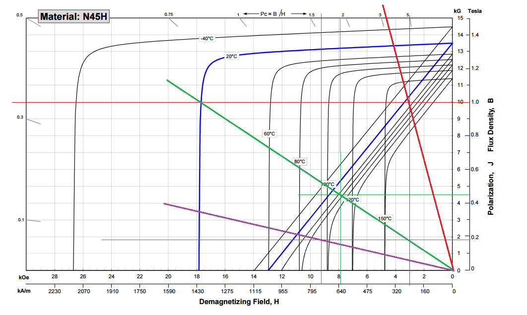
I did a rough simulation about the max operating point of N42 magnets with shape like we have in mxus motor. With rough i mean i did not had accurate numbers so i assumed a width of 13mm and thickness of 2,5mm. the 45mm length was clear but this has no influence.

the result: already at less than 60°C they will get partial damage.
if i interpreted the graphs right than at 80°C the strength would drop to about 50-60% of what it would have original

N42SH would hold its strength up to 115°C

this is one single magnet in free air WITHOUT the influence of the back iron, but what effect does it have?

EDIT:

flathill, when the magnets are attached to the back iron, they will have a max temperature operating point of one single magnet in free air with twice the thickness (assumed there is 100% steel return, with the rectangular magnets it will be lower). i am right with this?

a calculation with twice the thickness gives me a max op point of about 70-75°C
 
macribs said:
Suddenly there is another factor to read up on, the secrets of magnets. Even more technical english. :? :oops: :cry:

I saw one thread here where one did swap some magnets in a motor because magnets cracked somehow. Would it be possible to swap out all magnets with different higher quality magnets? What would be potential benefits swapping magnets? Other then higher temp handling.

What happens if one swap magnets with higher quality and stronger magnets? How will the characteristic of the motor change? Lets use the mxus 3K for this.
Will stronger magnets produce more or less torque? Would KV change?


However much magnet field moves past the teeth is how much BEMF you get. Decrease the magnetic strength, decrease the magnitude of BEMF.

It works backwards as well of course, stronger magnet makes lower kV (higher BEMF) which makes more torque per amp, but at the cost of reaching max RPM for a given pack voltage sooner.

Stronger magnets mean more core losses, but potentially less copper loss for a given amount of torque produced, so it really comes down to trade-offs for the given applications needs.
 
It's one of the reasons I was curious about cost for mass-producing finned rings. Are the rings usually iron, aluminum, or some combination of both?
 
Kodin said:
It's one of the reasons I was curious about cost for mass-producing finned rings. Are the rings usually iron, aluminum, or some combination of both?

You'd want aluminum.

On the magnets, I've done some testing but the grades are pretty variable. Once the temperature reaches the Curie point, they lose virtually all magnetism. Below that, the magnets degrade over time, degrading faster at higher temperatures. At 'normal' temperatures, the half-life is something like 22,000 years.

Up to the "maximum operating temperature", the magnets get weaker as they get hotter, but return to normal as they cool off. Another reason to avoid high motor temperatures.

Here is a good description of the temperature behavior:
http://www.kjmagnetics.com/blog.asp?p=temperature-and-neodymium-magnets
 
Would iron negatively affect the magnetic field? I have no idea how that works in modern motor designs.
 
fechter said:
Kodin said:
It's one of the reasons I was curious about cost for mass-producing finned rings. Are the rings usually iron, aluminum, or some combination of both?

You'd want aluminum.

Would you not ideally want thin lamination's of (slinky) good magnetic steel backing the magnets, cast into or shrink fit in the aluminum hub shell?
 
Most motors will have iron backing behind the magnets. This iron doesn't see a flux change so doesn't need to be laminated.
outside of the back iron, the magnetic field should be near zero, so adding more iron won't help (unless it was designed too thin to start with). About 4-5mm thickness is generally enough to not saturate. Beyond that, you'd want something with the best heat conductivity. Copper is really the best, but very heavy and expensive compared to aluminum.
 
liveforphysics said:
Stronger magnets mean more core losses, but potentially less copper loss for a given amount of torque produced, so it really comes down to trade-offs for the given applications needs.

Exactly. Here are a few illustrative examples from when I was doing earlier testing replacing the magnets in a Nine Continent motor with a set that was both weaker (2.6mm thick N35s) and strong (3.2mm N35s) than the stock magnets. The output torque per amp does improve a bit with the stronger magnets, and as a result there is correspondingly less RPM / Volt.
Output Torque vs Magnet Strength.jpg

However, much more striking is the effect on the no load drag torque to spin the motor. The additional core losses from the stronger magnets mean a much greater drag on the wheel compared to the thinner magnets, in this case by a factor of almost 2:


So though you may intuitively think that the strongest magnets will give the best performance, that's not going to be the case if part of the performance assessment is how easily wheel turns when you're just pedaling the bike. And since the peak efficiency value of a motor is determined more by the core losses than the copper losses, weaker magnets can mean a higher top efficiency, even though the efficiency under heavy load will be worse.

flathill said:
about magnet temp grades
a 120C N40 magnet is usually cheaper than 150C rated N35 magnet. The most expensive element in a neo magnet is dysprosium which give the magnet its temp resistance.

This is certainly what I noticed when getting custom magnets quoted for the motor. It would have been less expensive to get the N42 in the standard temperature grade, but since that increased the motor drag so much I stuck with the N35 and then choose to get the high temperature SH version with the money that I was initially expecting to pay for the higher strength grade. In light of these more recent temperature tests I'm glad that I did.
 
Hey guys, so Statorade made the final naming cut, and I've created a separate "for sale" thread here for those wanting to join the experiment party and get a 10mL syringe of the FF to try out in their motors
https://endless-sphere.com/forums/viewtopic.php?f=31&t=73818

We're still working out the final packaging details but I expect it should be ready for shipments to go out by the end of this week.
Statorade_Package.jpg
Any questions regarding the usage and application I would like to keep on that sales thread to avoid clutter here, and when people have experimental test data so share then with numbers and all, then this is the appropriate place for that.
 
If the FF is so effective at cooling , and say most times in normal street riding you are in stop start and not steady state conditions, hence most of the time the motor runs cooler.
So that it works so good that the winding temps on average are half with a motor that is half the temperature, say 160c without and 80 avg with FF.

What effect what this difference in temperature of 80 deg C have on winding resistance ? and more importantly efficiency ? will it make the motor more efficient and by how much if it it always 80 deg cooler ?
 
jk1 said:
If the FF is so effective at cooling , and say most times in normal street riding you are in stop start and not steady state conditions, hence most of the time the motor runs cooler.
So that it works so good that the winding temps on average are half with a motor that is half the temperature, say 160c without and 80 avg with FF.
What effect what this difference in temperature of 80 deg C have on winding resistance ? and more importantly efficiency ? will it make the motor more efficient and by how much if it it always 80 deg cooler ?

All is very accurately modeled here for whatever scenario your imagination can possibly contrive:
http://www.ebikes.ca/tools/trip-simulator.html

Use the top graph to sketch your elevation profile for a trip you want to simulate. Right click and drag on the bottom graph to select a section for showing stats, like your wh/mi efficiency. Left click anywhere on the bottom graph to put a cursor location, and hit the "show advanced" button on the right to show the instantaneous motor efficiency and winding resistance at that particular cursor point.

What you'll find is that the addition of Statorade won't have much of an effect at all on the wh/km efficiency unless you're in situations where the motor core was getting up in the 100-150oC regions, and then it can start to be a player. For instance here is a trip with 3 big hills (~13% grade) and a fairly with stock H3540 Crysatlyte motor. Core gets to 180oC by the end of the trip, motor is running at 67.5% efficiency at the cursor location, and the winding resistance is at 0.24 ohms, and the journey burned through 98.6 wh/km (would be way better if the "regen enabled" was checked, but motor would also totally overheat)
Exampe Trip Sim without statorade.jpg

And the exact same scenario with the only difference being ferrofluid in the core. Now we end the trip at 115oC, with motor running 71.4% efficiency, 0.20 ohms phase resistance, and using 93 wh/km for the run, compared to 98.6 wh/km previously. [EDIT - there currently seems to be a bug in the battery watt-hours accumulating summation since the numbers are about 3x too high, these should be more like 33 wh/km vs 31 wh/km. Will get this fixed ASAP, although the comparative results are more or less correct]
Exampe Trip Sim with statorade.jpg

In ride simulations where the motor isn't getting very hot, then yes the performance difference in your mileage and efficiency is rather marginal.
 
Sorry to derail, but assuming you went to higher grade magnets, would a thinner lamination stack help? IE: going from 0.35mm to 0.20mm lams? I realize popular manufacturers haven't gone to that lam thickness yet for the larger hubmotors and it'd mean ~$10,000+ USD in tooling costs to get a manufacturer to start making them, but I'd bet it'd cut down on iron loss a lot while yielding higher torque.
 
Kodin said:
Sorry to derail, but assuming you went to higher grade magnets, would a thinner lamination stack help? IE: going from 0.35mm to 0.20mm lams? I realize popular manufacturers haven't gone to that lam thickness yet for the larger hubmotors and it'd mean ~$10,000+ USD in tooling costs to get a manufacturer to start making them, but I'd bet it'd cut down on iron loss a lot while yielding higher torque.

I think I've heard that some magnets suppliers will make custom magnet to suit your needs, so if you make a 3D image of the magnet size they can cut each magnet to right size for you. They can choose magnet specification you desire, so getting custom made magnets with higher quality or much higher temperature tolerance should be possible. The net price I suspect will be rather high for such custom magnets, but compared to having a motor manufacturer making a custom run of say 100 pieces of motors with custom magnets I am certain the price for just the custom magnets will be acceptable.

Seems for powerful hubs the three most popular motors are mxus 3000, cro and QS 205. Maybe we could do a group buy of magnets if there is enough interest so that we could get lower prices?
 
Each of the motors you listed have the exact same magnets?

Perhaps there is enough of an interest, and enough people willing to take off old magnets for whatever the benefits are for stronger magnets. Why wouldnt cutting oversized magnets down to size work? Does it lose its magnetic strength?
 
justin_le said:
So though you may intuitively think that the strongest magnets will give the best performance, that's not going to be the case if part of the performance assessment is how easily wheel turns when you're just pedaling the bike. And since the peak efficiency value of a motor is determined more by the core losses than the copper losses, weaker magnets can mean a higher top efficiency, even though the efficiency under heavy load will be worse.

Yes for an ebike you need to pedal the strongest magnet may not be optimal. I attached a paper on mechanical flux weakening. Yes you can eek out some gains in efficiency, but overall it doesn't seem worth it, even if it was practical, which it is not.

Interesting reading in any case for those of your who want to learn more about the effects of what happens when your magnets get weaker when they heat up (similar effect to larger airgap).

View attachment axial_flux_variable_gap_motor.pdf

----
increased overall efficiency is only part of the equation with the addition of FF. Your motor is going to last a lot longer if you keep the winding cool with FF. A general rule of thumb is every 10C decrease in winding temp results in a doubling of magnet wire insulation life. Or put another way every 10C increase in winding temp cuts insulation life in half.
 
Kodin said:
Sorry to derail, but assuming you went to higher grade magnets, would a thinner lamination stack help? IE: going from 0.35mm to 0.20mm lams? I realize popular manufacturers haven't gone to that lam thickness yet for the larger hubmotors and it'd mean ~$10,000+ USD in tooling costs to get a manufacturer to start making them, but I'd bet it'd cut down on iron loss a lot while yielding higher torque.

Thinner laminations only affects the slope of the torque vs RPM curve, it doesn't affect the offset or drag at low speeds which is determined mostly from the hysteresis losses of repeatedly reversing the magnetic domain in the stator. Stronger magnets will increase both the hysteresis and the eddie current core losses, and it's only the eddie current losses that would benefit from then using thinner steel. You'll have noticeably more drag at low speeds regardless.

But this is totally not the thread for a general talk about motor magnets unless it's specifically related to motor heating effects, so I'll answer this question once now, but any further talk about general magnets and lamination thickness stuff and group buys please take it to a different topic since it doesn't belong here.
 
thank you for offering the FF justin. thats great.

i know the thing with the magnets should be discussed in another thread, but could we specify a max temperature operating point at least for MXUS motor? i feel a bit left alone with that problem right now because nobody has comment about the values i got from the magnet calculator. there is no doubt that flathill has big knowledge so i hope he can comment.

If the magnets that are placed side by side on the rotor would have 100% steel return throgh this back iron, could we calculate it like one single magnet with TWICE the thickness?
As it is fact that two stacked magnets with for instance 2mm thickness will behave same as one sinlge magnet with 4mm, it would make sense for me.
How than could we calculate if they have lets say 95% return to the rotor (because of rectangular form and glue between) and 85% in direction to the stator because of the airgap?
 
madin88 said:
thank you for offering the FF justin. thats great.

i know the thing with the magnets should be discussed in another thread, but could we specify a max temperature operating point at least for MXUS motor? i feel a bit left alone with that problem right now because nobody has comment about the values i got from the magnet calculator. there is no doubt that flathill has big knowledge so i hope he can comment.

This is totally valid and relevant, and ideally the either the manufacturer MXUS and/or the people who are in business of selling their motors could comment on the specific magnetic specification and max operating rotor temperature. Lacking that, I could sacrifice one of the sample mxus hubs that I have here to putting it in the oven at increasing temperatures and measuring the motor KV at each stage, to find at what temperature there starts to be a permanent demagnetization. In this case it would be the whole motor, and so with the stator in place it would have a higher max operating temperature than you'd have with just the motor shell as you did in the oven. The results from this test would then give us some concrete numbers for the suggested thermal rollback point of a FF filled core.

If the magnets that are placed side by side on the rotor would have 100% steel return throgh this back iron, could we calculate it like one single magnet with TWICE the thickness?

To a first order approximation that sounds plausible to me but I'm no magnet expert. If you have a gauss meter, then you could measure the field strength right at the surface of the magnet while it's on the steel backing, and then compare that with the field strength of 2 stacked magnets with no steel ring. Presumably if the measured Tesla's are the same then they are at a similar operating point and the assumption is reasonable.
 
I was curious about the oven with no rotor. I had Biff/Fetcher's 9C model and did a quick sim with and without the rotor

N45H (120C) magnets

rotor in place (M15)
back iron in place (pure iron)
no current in any of the phases
B=1.0 T
H=233 kA/m


rotor REMOVED
back iron in place (pure iron)
no current in any of the phases
B=0.45 T
H=635 kA/m


single magnet segment in free air
B=0.17
H=840 kA/m


note all the lines are roughly drawn and the accuracy is not guaranteed. the mxus is different. this was just a quick experiment to show the effect of removing the rotor. the only way to really know is to test the motor

note the load line is drawn from zero zero to the intersection of the calculated B and H. Where this line intersects with the normal load line is the normal working point. The magnet will suffer permanent demagnetization if this point is below the knee on the normal curve.

You can see with the rotor in place the "120C" rated magnet would not demagnetize even in a 150C oven, but real world in the 150C working motor it might demag, as the load line moves when the electromagnets (the stator) are active. to really find the limits of the motor you need to test in under a wide variety of operating conditions. you could probably simulate controller field weakening but it is better just to test, especially without 3D FEA software (end effects)

http://i.imgur.com/ePpg0lf.png


ePpg0lf.png
 
justin_le said:
Kodin said:
Sorry to derail, but assuming you went to higher grade magnets, would a thinner lamination stack help? IE: going from 0.35mm to 0.20mm lams? I realize popular manufacturers haven't gone to that lam thickness yet for the larger hubmotors and it'd mean ~$10,000+ USD in tooling costs to get a manufacturer to start making them, but I'd bet it'd cut down on iron loss a lot while yielding higher torque.

Thinner laminations only affects the slope of the torque vs RPM curve, it doesn't affect the offset or drag at low speeds which is determined mostly from the hysteresis losses of repeatedly reversing the magnetic domain in the stator. Stronger magnets will increase both the hysteresis and the eddie current core losses, and it's only the eddie current losses that would benefit from then using thinner steel. You'll have noticeably more drag at low speeds regardless.

But this is totally not the thread for a general talk about motor magnets unless it's specifically related to motor heating effects, so I'll answer this question once now, but any further talk about general magnets and lamination thickness stuff and group buys please take it to a different topic since it doesn't belong here.

Fair enough; sorry, just really interesting stuff and it keeps bringing up more questions the further we go with this. I'll try to stay on-topic from now on. :)
 
made_in_the_alps_legacy said:
so... for a given motor and a given core max temperature how much power increase does the statoroïd brings, Justin ?

Again, great thing about having this modeled. Let's say the max core that we'll allow is 120 oC, and we'll make an arbitrary hill to climb that is 1000m high and 20km long (ie 5% grade for 20 km), and use the Crysatlyte H3540 hub. I set the speed limit to 40 kph so we're comparing with the motors constant velocity, and then I keep adjusting the vehicle mass until at the 20km point the core temperature is 120 degrees. In this case, that happens at exactly 102 kg, and at the motor power output during this trip is 949 watts.
120 degrees with no Statorade.jpg
Now I change nothing to the simulation except choose the hub with Statorade. At first, this yields a final stator core temperature of just 74 degrees, so then I keep increasing the vehicle mass steadily until finding the point where the temp is again at 120, and presto this happens with a vehicle mass of 161 kg. The motor output power during the course of this simulation is 1302 watts.
120 degrees with Statorade.jpg

So the addition of ferrofluid increased the power capability by 350 watts or just under 40%, allowing the bike to pull an extra 60kg (130lb) of load up the climb.
Other situations can be higher or lower than that. If you do a simulation at high powers but over shorter distances, then it's a much smaller 10-20% improvement since we're still mostly in the heat capacity realm. But if you allow the simulation to run long enough to truly reach steady state (extend the graph to like 50+km for this), then it gets closer to +45%.
 
Thxs I think I get it,
maybe not more than 20% more for transient thermal excursion because the heat capacity drives the cooling heat transfer,
and up to 40% and more in steady state when the heat transfer settles and the heat capacity influence becomes less relevant in the cooling heat transfer
 
Wondering how much benefit adding external fins would do in your hill climb simulation example. I could see them adding possibly big benefits in stop and go or slow speed heat shedding but not sure they would add very much at speed. Certainly would help in warmer weather. These factors alone make it a interesting next step to evaluate. Serious increase in motor robustness with just a few drops of substance. :D
 
Back
Top