BMS's That are Available NOW

PJD

100 W
Joined
Nov 1, 2007
Messages
232
Location
Pittsburgh, PA, US
I write this with a bit of trepidation, as I don't want Bob Mcrees development efforts to come to naught, but due to health issues, his BMS will probably not be forthcoming anytime real soon.

There has been lots of dscussion about design concepts, vague vapor-proposals, and proposed products that open with great fanfare, get to the prototype testing phase, only to become duds.

What simple, affordable, no frills BMS's are available for 16 cell and larger systems right now or on some kind of firm time frame?
 
You can get a Ping BMS for $47 plus $15 shipping. This is the 16 cell version. He also has a 10 cell version for less.
Ping bms shunt.jpg
 
I am not very happy with Gary and Bob's BMS situation. If he is ill, that's another story. I am sure they could at least answer my PM's! Anyway, does the Ping 16 ch. BMS cover charge shunting or just LVC and maybe some balancing? Were can I get more info on this? Is there a site? Does Ping supply a schematic so you could actually fix it if damaged without sending things back and forth to China? Will this thing work with A123? What voltages for low and high?
Jeff K. "Deep Cycle" project
 
I am also a bit ticked off about the Bob and Gary BMS situation. I am entirely understanding of Bob's health situation, but perhaps Gary can provide us with the Express PCB design files and ordering info and parts list for the various versions of the BMS so we can move the project forward independently of Bob, or Gary.

Gary, is this possible?

As far as the ping BMS, there are some unknowns surrounding them as Jeff K mentioned. As a minimum, I would want to avoid wiring the battery power circuit through them - bypassing the (too-low) current limit, and rig the low voltage cutoff logic directly to the throttle or controller logic.
 
PJD said:
As far as the ping BMS, there are some unknowns surrounding them as Jeff K mentioned. As a minimum, I would want to avoid wiring the battery power circuit through them - bypassing the (too-low) current limit, and rig the low voltage cutoff logic directly to the throttle or controller logic.

That's what I was thinking also. It should be fairly easy to interface the LVC to the brake input so you can discharge straight off the cells. Something similar for charging.
 
between Gary Goodrum, Bob Mcree and Randomly (whoever the heck he is) there are enough circuit fragments to design a complete BMS.

the BMS consists of the following circuits:
1. A LVC to prevent over discharge.
2. a HVC (high voltage cutoff) for charge termination and to prevent over charging
3. cell balancing.
4. current limiting to protect from over discharge

to this can be added optional modules such as an active power cut off using fets.

what i propose is to create an open source design that is flexible enough for all of us to use on just about any size pack. i would opt for making the module boards sized for 12V nominal 4S packs. if you need a 24V pack you would build 2 modules, 48V would require 4 modules etc. these modules would be designed to be daisy chained together.

the LVC can be based on the circuit proposed by Randomly. the Charge termination circuit would again be from Randomly, the cell balancing could be the circuit from Bob Mcree even though i hate the thought of all of those trimmers to set. the max discharge protection could be very simple and set by a a network of parallel PTC (POLY) fuses selected for the maximum value.

the boards could be laid out either by using PCB Express or PCB 123. and enough of us would have to get together to purchase a run of these boards.

last we need someone with the time and inclination to keep the whip cracking and shepherd the project.

rick
 
rkosiorek said:
the boards could be laid out either by using PCB Express or PCB 123. and enough of us would have to get together to purchase a run of these boards.

Do not use PCB 123. I tried their free software, and it crashed on me when I tried to save a design. Wish I could get those 3 hours back.

There are two other PCB services that have similar names, but are different companies.

PCB Express does not offer free software for creating boards.

I used Express PCB's free software and love it. It does the job without crashing, and I think it is easier to use. Schematic software is included with Express PCB.

http://www.expresspcb.com/

I'd be happy to work on PCB layout.
 
I use ExpressPCB, and their service is fast and accurate. The free software has been flawless. I will be happy to pass on the existing PCB files to whoever wants them, but it is going to need some major surgery, I think. The best option I can see is to use randomly's circuit mod for the charger control section, which keeps the shunts right at the cutoff point, and so this should drastically reduce the heat generated by the TIP105 power transistors. I'd also change the LVC active cutoff portion of the circuit to what randomly proposed, but I'd still use the opto outputs, It is simpler and cheaper this way, plus it works. :)

The other thing that needs changing is to add the LEDs back in, for each channel, if that is desired. The last version of the layout I did (v1.14...) had those removed. The board will have to be slightly wider, but it is not such a big deal to put them back in. Personally, I question their usefulness, but others like lots of lights I guess. :)

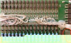
On another front, I finally got some time to do some testing with my switched capacitor prototype balancer. The main part doing most of the work is the LM2663 SMD, along with a 10uF multi-layered ceramic cap. The rest is just a couple of op-amps which are used to drive a two-color LED. When one cell is significantly above the cell adjacent to it, the LED is either fully red or fully green. If the cells are reasonably balanced, both colors are lit, and the color is yellowish. In the picture below, I've populated enugh of the board to do three cells. There are three a123 cells connected, with two of the cells fairly close, and one that is quite a bit lower:

Switched%20Cap%20Balancer-01.jpg


So far, it appears to be working, and the cells are balancing. I don't know how long it will take just yet. The chip/cap combo is able to move a max of about 200mA between cells. The little LM2663 parts are definitely warm, but not too hot that you can't leave your finger on them. Anyway, this will be an interesting test. If it works, and the cells balance in a reasonable enough time (couple of hours for a 10Ah pack...), I will go ahead and make a complete balancer. I've also figured that I could turn this into a BMS by adding the LVC portion, plus some logic to put the LM2663 chips in the sleep mode unless the charger is connected, and if the cells are all above the LVC set point. Way too early for that, though, as I still don't know how well this will work.

For those looking at Ping's BMS board, richard had a suggestion in the other thread that you could up the current limit by filling in the shunt resistors with some solder. I think it is better to simply bypass both the current limiter and the LVC active cutoff, and just tie the existing cutoff logic into the controller ebrake line, as suggested. Shouldn't be that hard. The balancer portion only disappates about 50mW per channel, so plan on leaving the charger connected for a day, or so, if you are lookig to balance a big capacity pack (30-40 Ah...).

-- Gary
 
"The balancer portion only disappates about 50mW per channel, so plan on leaving the charger connected for a day, or so, if you are lookig to balance a big capacity pack (30-40 Ah...)."

But is the Ping BMS balancing full-time, so when you charge the pack, it is already essentially balanced?
 
PJD said:
"The balancer portion only disappates about 50mW per channel, so plan on leaving the charger connected for a day, or so, if you are lookig to balance a big capacity pack (30-40 Ah...)."

But is the Ping BMS balancing full-time, so when you charge the pack, it is already essentially balanced?

No, the balancer circuits are only enabled when the charger is connected. That's why he suggests leaving the pack connected to the charger, with the green LED lit, for 10 hours, or more.
 
No, the balancer circuits are only enabled when the charger is connected. That's why he suggests leaving the pack connected to the charger, with the green LED lit, for 10 hours, or more.

But meanwhile, while charging, (especially the first time) some cell voltages are going way over the desired 3.7 volts...

The ping charger is looking less viable all the time.

Since I am thinking of fan cooling for the BMS in my application, I think the existing Bob Mcree design may work fine for now. Most users don't need a maximum discharge protection as the motor controller and, if desired, a simple fuse, do that job fine.

But, as far as another really-existing (but a bit expensive) alternative - Gary's LVC with the TP210 balancers, used off-board, for balancing. Gary, How much power per cell do the TP210's dissipate?
 
PJD said:
But meanwhile, while charging, (especially the first time) some cell voltages are going way over the desired 3.7 volts...

The ping charger is looking less viable all the time.

Since I am thinking of fan cooling for the BMS in my application, I think the existing Bob Mcree design may work fine for now. Most users don't need a maximum discharge protection as the motor controller and, if desired, a simple fuse, do that job fine.

But, as far as another really-existing (but a bit expensive) alternative - Gary's LVC with the TP210 balancers, used off-board, for balancing. Gary, How much power per cell do the TP210's dissipate?
`

The TP-210Vs do 450mA of discharge current, which is one of the reasons they cost a bit more. I also have access to the Hyperion LBA10 balancers, which can do 6 cells, but two can be connectedtogether to do 12 cells. These are about $42 each, but you will need three of them to do 16 cells. I think the discharge rate is about 350-400Ma per cell, but I'm not sure. For an even less expensive option there is always the AstroFlight "Blinky". These too are good for up to 6 cells, so you'd need three, but they are only about $30 each. These will discharge each cell at a max rate of 150mA.

-- Gary
 
Gary,

I'm in the process of breadboarding your schematic and noticed from the LM2663 specifications that the ESR value and type of the capacitor is critical in the overall performance of the design. Can you tell me the model and/or order number of the capacitor used in your design?

Rod
 
rsmithaa said:
Gary,

I'm in the process of breadboarding your schematic and noticed from the LM2663 specifications that the ESR value and type of the capacitor is critical in the overall performance of the design. Can you tell me the model and/or order number of the capacitor used in your design?

Rod

He mentions using multi layer ceramic caps - these are very good, low ESR caps. Just do a parts search on digikey using "MLCC cap", then further select the capacity (10uF) and the voltage using their great search tool. Go through the list this gives and find the cheapest part available in bulk or cut tape (and in stock!) - prices for very similar MLCC's can vary a lot! Also make sure you get the lowest voltage parts you need for the job, as this will save you money. MLCC's are very resistant to overvoltage spikes, BTW, so the cap's rated working voltage can be very close to your circuit's actual steady-state voltage (whatever that is in this case).
 
Remember that if you use multiple 6cell balancers (like a blinky) on larger packs (like a 16cell) you will end up unbalanced in the long run if you dont overlap the balancers.

example:

Cells 1-6 hooked to blinky #1
Cells 7-12 hooked to blinky #2
Cells 13-16 hooked to blinky #3

This would end up with 3 groups of cells that are out of balance with each other since the balancers do not communicate. I have experienced this in real life and the cheaper your packs are the quicker this will happen. I use lipo cells from China and after only 20 or 30 cycles I see the (in my case) groups of 6 out of balance (I run 24S, 4 groups of 6)

I have fooled around with overlapping cells like this:

Cells 1-6 hooked to blinky #1
Cells 6-11 hooked to blinky #2
Cells 11-16 hooked to blinky #3

Where Cells 6 and 11 bridge the balancers. There are potential problems here depending on the balancer. In the end the cells will be balanced but it is possible that it could take longer / burn more amphours to get there due to the race condition on the overlapped channels. One trick would be to de-solder one dump resistor on one balancer on the overlap channel but I have not tried this and it would be highly dependent on balancer design.

LVC should not be an issue if you never deep discharge
HVC should not be an issue if you use a quality charger
Balancing is the real trick IMHO

-methods
 
:arrow: What would be the most cost effective four SLA cell balancer?

It need only balance on runtime as I can deal with charge balancing by reconnecting the wires. (I charge at 12 volts anyway) Once the wires are connected for runtime I'd like to be sure that I don't have any "runts" anymore.

Think cheap... really cheap... :)
 
safe said:
:arrow: What would be the most cost effective four SLA cell balancer?

It need only balance on runtime as I can deal with charge balancing by reconnecting the wires. (I charge at 12 volts anyway) Once the wires are connected for runtime I'd like to be sure that I don't have any "runts" anymore.

Think cheap... really cheap... :)

http://www.evsource.com/tls_powercheq.php
They have discharge balancing. Grab 3 units for 4 batteries. Only $175 and 4 weeks wait.

These are designed for full sized EVs. I'm not aware of any other options. They might sound expensive, but if you need to protect a pack made of 200Ah batteries it can pay itself off easily.
 
voicecoils said:
Only $175
Cough, cough.... um.... yeah...

I was thinking more like $20 somehow. :(

Hmmmm... any other ideas out there?

(I appreciate the effort :) )

The SLA's I'm looking to balance are only 18Ah.
 
Ypedal said:
If your SLA's need ballancing.. you need new SLA's !!.
True for charging... but for runtime the "runt" cells lower capacity means that it repeatedly reaches a lower voltage before the others. This eventually wears them out.

A runtime balancer would extend the life of SLA's a great deal.

I actually have done some rewiring so that my SLA's are in parallel now (2x2) and they balance each other, but I might not want to keep this configuration forever and would like to think of other options.
 
Ypedal said:
By how much runtime ?
It's a progressive disorder... at first maybe all the cells end near the same, but as time goes on they start to diverge and the "runt" cell is forced to continue to operate at lower and lower voltage relative to the other cells.

So maybe at first you end with:

12.1, 12.2, 11.9, 12.1

...but after a thousand miles it's:

12.2, 12.4, 11.0, 12.3

...which you can see means that the stronger cells are actually getting less and less of a workout as the weaker cell does more and more.

When things get really bad it gets like:

12.5, 12.6, 10.2, 12.5

...and your range is about half of what it once was. If you can runtime balance the cells then the stronger one's help the weak.

I mean come on... we just elected Obama... you have to understand how this works. :lol:

(spread the wealth)

If there was a really cheap way to balance SLA's you would extend the life a great deal because you would tend to even out the wear across all the cells rather than sacrifice one "runt" at a time to an early death.

Even a small home built project might be okay... as long as it's cheap... the switched capacitor approach is the best because it allows all the energy to be retained. Resister based solutions are a waste of energy so rather than sharing the wealth you are just wasting the wealth... not good for batteries or governments. :wink:

Capacitor_BMS.jpg
 
You and your 5800 posts know better already.. ( we have been there and done that before, but here i go again )

Using words like " So maybe at first you end with: 12.1, 12.2, 11.9, 12.1"

Means you don't actually have this problem, but you " might " in a potential way.. many things could " maybe " happen in your daily life.. but to stay on topic.

- If durng the last km of your ride, one cell drops out before the others are empty, that's par for the course.. consider that the limit of your pack if used to it's maximum potential. ( something you should avoid with SLA to begin with )

- If one cell drops out WAY before the others, then replace that one bad cell with a good one, expect this one cell to last longer than the others but it's an acceptable compromise vs buying a whole new pack

- Because one cell dies before the others, makes no difference on the others in series other than ending up with lover ovreall pack voltage and less speed.. keep pulling amps thru an empty cell and you will kill it. simple.

A cell with slightly lower capacity can remain in a pack but a " Runt " as you like to call it.. aka: severly lowe capacity, preventing the pack from being used properly.. should not remain in a pack at all.. this rarely happens in real life.

If you encounter frequent " runts " in your packs, you are abusing your pack or are not charging it properly.. or have really crappy cells to begin with.
 
Ypedal said:
If you encounter frequent " runts " in your packs, you are abusing your pack or are not charging it properly.. or have really crappy cells to begin with.
:arrow: No, I totally don't agree.

If anything we've learned (I've learned) that all cells of all chemistries will have minor differences and as time goes on those differences magnify until you lose one "runt" out of a group that is otherwise strong.

Doctorbass has even made a hobby of collecting so called "damaged tool packs" that actually just have one bad cell within multiple. So the reality of individual "runt" cell decay is very certain.

The question ultimately becomes one of price-to-performance.

How much is it worth it to spend $100 for a balancing system when for this type of battery the cells themselves only cost $100?

If there were a way to do raw SLA with a balancer for about $20 you could really extend the life of the cells because you would slow down the rate of differentiation.

In batteries "the rich stay rich and the poor get poorer and die".

On my SLA bike now I've already gone to a "post balancing" wiring configuration that automatically self balances just by using series-parallel tricks, but I'm still interested in a more simplified SLA balancer.
 
I am truly confused. Since when did cell balancing apply to SLA Battery Packs ?

Don :mrgreen:
 
Back
Top