Definitive Tests on the Heating and Cooling of Hub Motors

MrDude_1 said:
justin_le said:
spinningmagnets said:
Ester is the base material for aircraft hydraulic fluid...low smoke...low flammability...thin fluidity.

It also smells a bit funny, wheras the synthetic oil base has no odor at all. But otherwise in all performance and behavior tests I can't really tell the difference, though I should clarify most of my recent experiments were with the synthetic base since that was the bottle the I had had opened and received first.

Working with engines, I notice a diff between ester base and synthetic varnishing... but this is at at higher temperatures... something these hub motors will never see.
Did you ever do any oven testing?


http://www.bobistheoilguy.com/esters-in-synthetic-lubricants/

Esters are the synthetic motor oil base when cost is no object. Esters are the synthetic motor oil base for jet engines and formula cars etc.

PAO bases are most commonly used in cheap 'synthetic' oils as a cost savings not a performance improvement over esters.

As a fluid to remain stable and not vaporize or congeal while hot and getting sheered, esters are about as good as is known to exist (without getting $$$ exotic with fluropolymers, and even then my still not be better than the right esters).
 
liveforphysics said:
http://www.bobistheoilguy.com/esters-in-synthetic-lubricants/
Esters are the synthetic motor oil base when cost is no object. Esters are the synthetic motor oil base for jet engines and formula cars etc.
PAO bases are most commonly used in cheap 'synthetic' oils as a cost savings not a performance improvement over esters.
As a fluid to remain stable and not vaporize or congeal while hot and getting sheered, esters are about as good as is known to exist (without getting $$$ exotic with fluropolymers, and even then my still not be better than the right esters).

I should have been more specific. Two stroke engine oils. Those dirty nasty things that actually burn the oil. Thats where I see the huge difference.
The most often used example is Castor Oil Esters... they work amazingly well, but they LOOK dirty because of the varnish they leave behind... However there are other Ester based oils used by top tier MX teams (back when we actually ran 2strokes)
Synthetic oil often appears cleaner, and smokes less... but doesnt work as well as a lubricant.

In the hub motor case, I dont THINK there would be any diff between them... but I have this nagging thought in the back of my head of pulling a motor cover and seeing the stator coated like a 2 stroke bottom end.. a nice golden amber over everything.
 
Lubrication is not what we need or are after here. Heat transfer is. Ferro fluid with (EG) glycol base possible? Near double the heat transfer in pure form.
Liquid metal possible? Near off the chart!
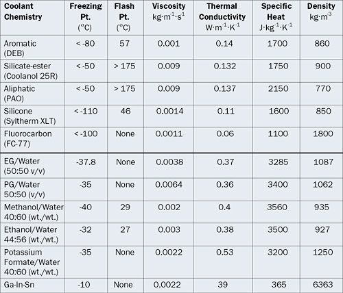
http://www.electronics-cooling.com/2006/05/an-overview-of-liquid-coolants-for-electronics-cooling/
2006_May_A2_Table1.jpg
 
Graphite can have amazingly high thermal conductivity. If there were carbon brushes between the stator windings that rubbed on the inside of the shell, it could be very effective. Not easy to implement though.

Helium II liquid is really off the charts, but if the motor is that cold it would probably be superconducting.

Liquid metal would be bad since it's electrically conductive. Eddy currents from the moving magnets would be like a shorted stator winding.

Ethylene glycol may possibly work as a ferrofluid base but would be prone to evaporation.
The esters seem like the best thing out there.
 
Interesting point on the carbon. Nano tubes in the fluid mix may add thermal conductivity but also electrical. Ethylene glycol also is not dielectric. One of the dielectric oils most likely best place to start the long term testing.

We talked about oil additives before when we were talking oil vs air alone, page 8 of this thread. I noted HBN (hexagonal boron nitride) as used to increase thermal conductivity of heat transfer oils. Not sure if this is worth exploring as a additive to the secret FF base mix. :p
 
Carbon nanotubes mixed in might be good. Since they're long and skinny, they won't create eddy currents unless you have so many they make a circuit. I think Luke had some :twisted:

You could test it by sticking your ohmmeter probes into it and see what the resistance is. It would need to be very low resistance to create a problem.

Any additive would need to stay suspended. The same surfactant used for the FF particles might work.

Are there magnetic carbon nanotubes?
 
I don't know if it would help to contain the FF in and around the footprint of the magnets (vs is splashing outside the flux area) but I sense you could mount wiper/seal on each side of the laminations (could actually wind over it as an added layer to the lam stack. It could be fr4 ring with gasket or oring material on the circumference

In this case, the seal would be stationary and the magnet ring would rub up against it. And it would be softly rubbing axially against the edge of the magnets or magnet ring or radially against the bare steel next to be magnets on the magnet ring. That should help a lot I would think to contain the FF but idk if that's good or bad for heat transfer
 
justin_le said:
Back on the topic of test results, I'm finally working on the thing that has me most excited, which is testing out the ferrofluid effects on one of the prototype Grin motors. For those who don't remember, this one has a 2.5mm gap space between all the magnets, and so the behavior of the FF could be quite a bit different than when the magnets are butted up against each other.
file.php


In this case, rather than doing it just at 200rpm, I'm testing the stator->core conductivities at both 200 and 400 rpm in case the higher motor speed causes centripetal forces push the FF away from magnets and air gap and flat against the back iron instead.

And here after a full 22 runs in the wind tunnel under all different scenarios I have that data, and it continues to be exciting. Here's the most essential summary.
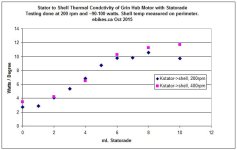
Grin Hub mL FF vs Conductivity.jpg

The 2mm gap space between the magnets rather than having them butted up did not drastically increase the amount of fluid fill required. At 2mL you start seeing some improvement and then it reaches full benefit at 6mL. As well, the concern that at a higher 400rpm rotational speeds the Statorade would be "squished flat" against the back iron rather than bridging the stator/magnet gap also proved unfounded. The 400 rpm curve seems to line up with the 200rpm curve pretty well even with the large gap between magnets which the FF could easily recess into.

You'll also notice here that the final thermal conductivity is even higher than it was on the wider MXUS motor (10 Watts/degree vs ~7 W/K https://endless-sphere.com/forums/viewtopic.php?p=1106508#p1106508). That's mostly a result of the fact that there I was measuring side cover temperature with the MXUS motor, but here I was using an IR sensor pointed right at the steel back iron ring, with the effect that we'll have higher core->shell conductivity numbers but worse shell->ambient , since the definition of the shell temp isn't quite the same.

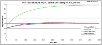
The following graphs really help illustrate what was going on. With no practical ferrofluid fill, the motor core temperature with ~95 watts of heat rose to nearly 70 degrees C, while the side cover and steel back iron temperatures were all very close to each other, the side plates ~31oC, and the steel rotor ring ~33oC.
Grin Hub Temp Rises with 1mL.jpg

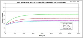
With the exact same test conditions using FF, the motor core only reaches 44 degrees, but the temperatures on the shell are now much more spread out, with the steel ring being at 35 degrees and the side plates 27-29 degrees.
Grin Hub Temp Rises with 7mL.jpg

This is what we'd expect with a majority of the heat flow now going through the magnets and back iron, but it's especially exaggerated in this particular hub design. Remember that I actually did most of the design and tooling of this motor in 2010/2011 and at that time heat flow wasn't a high priority on my mind. The goal instead was complete material removal and weight reduction, and so while most motor rotors have a thick (~6mm) ring of back iron surrounded in cast aluminum, in my case I made the steel ring taper as thin as possible before it met the side covers since there was no need conducting magnetic flux over there. And I did away with an aluminum casting altogether, instead putting the spoke flanges on the side covers.
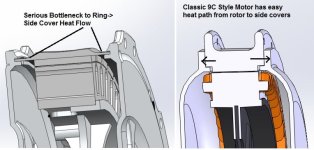
Grin Hub vs 9C Heatflow Path.jpg

The effect as you can clearly see is that there isn't much of a conductive pathway for heat to move sideways from the steel back iron to the side covers, and so we see this much larger 7-8 degree temperature difference vs ~4 degrees that was measured with the MXUS/9C/Crystalyte motors. This also means that the addition of an inside rotor fin would have more of a beneficial effect on the Grin hub compared to a regular motor that can more effectively transfer to the side covers.
 
That sucks about the lightweight design not having good contact to the side plates

Maybe you can add an external heatsink to the steel rotor shell that will also increase contact with the side covers (thermal bridge)

The side plates are too big to go to "waste" and internal fins will only offer a slight improvement
 
flathill said:
That sucks about the lightweight design not having good contact to the side plates

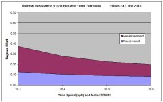
Well I wouldn't go so far as to say that it sucks in a tragic sense. There is still a massive enhancement from adding the FF, just not quite as much as if the side covers were really well thermally linked. Here are the results plotted as a function of wind speed and RPM (rpm = 10x wind speed) in terms of the total thermal resistance to ambient.

No ferrofluids:

and with 10mL of Statorade
Grin Hub Resistance Plot 10mL.jpg

At 10 kph/100rpm things improve from 0.62 to 0.37 degrees per watt, and and 40 kph/400rpm they improve from 0.36 to 0.2 degrees per watt. It's a 70-80% improvement, but with proper thermal linkage from steel to side plates this could be more like a 100% improvement (ie, twice the conductivity / half the resistance).

Maybe you can add an external heatsink to the steel rotor shell that will also increase contact with the side covers (thermal bridge)
If I had the benefit of foresight, I would have designed the side covers to have a much longer overlap of the steel ring (kinda like the TDCM and BionX hubs, but still leaving steel exposed in the mid section). That way the entire thin ~1mm steel section of the ring would have like 2mm of aluminum outside of it. This would add a small amount of weight for sure, but since aluminum has 4 times the conductivity of steel, the net effect would be about 8 times better conductivity for heat moving sideways from the steel backing plate to side covers over this stretch, as well as a much larger interface area for the steel->aluminum transfer.
However, I can't really complain, since what I thought was a motor design that was fundamentally a bit flawed for lack of thermal mass to absorb heat is now going to be a fine contender, even if it's not as FF optimized as it could be.
 
For sure. This is great news. Most importantly FF works with spaced magnets. I was really unsure of this myself given the centrifugal force. Thank you!

I was just thinking there could a 2 in 1 improvement since we were talking about the effect of a bolt on external heat sink. The bolt on heat sink could make contact with the side covers maybe. Not sure if this is practical as I dont have the motor in front of me. This could be an add on option. Long term now we know to use aluminum shell finned on all sides for sealed motors with FF
 
flathill said:
For sure. This is great news. Most importantly FF works with spaced magnets. I was really unsure of this myself given the centrifugal force. Thank you!
Yeah I should probably run it up to 600rpm too to see if there might be some speed where we notice this. But 400rpm corresponds to about 55 kph, and that's a sensible upper speed expectation for most users of this motor.
The bolt on heat sink could make contact with the side covers maybe. Not sure if this is practical as I dont have the motor in front of me.

Yeah I got that, get the advantage not just of an additional fin to the air but also of conducting the heat over to the side covers to make better use of all their exposed surface area. Unfortunately the side cover design doesn't have a nice mating surface for connecting with an inner bolt-on fin, but I'll definitely be looking at ways to possibly bridge this. And reworking the original mold tooling for the side cover plates isn't totally out of question, since this is adding aluminum = removing more metal from the mold which is usually doable at much less cost than a new mold. I do have 1000 pcs of these side plates to use up first though :D
 
If a motor does require a heat sinking profile on the covers I keep thinking a pin-fin arrangement would be best due to the rotation of the motor Vs. the linear oncoming cooling airflow.

For those concerned about long-term stability of FF a simple but easy test for someone with a few spare ebike components would be to just run a bare motor with FF continuously in a test stand in the garage powered by a mains PSU for a while. It'd be warm, quickly rack up the miles in a few weeks and only use a modest amount of electricity. It wouldn't simulate warming/cooling cycles or long-term environmental corrosion issues, but it would test thermal stability and shear resistance and hopefully dispel any concerns about abrasion.
 
why after such a success to built a highway for the heat to get out from the hub, ones would want to let that heat take turns to the side covers... better would be to dump that heat when the heat flux is still high - at the steel ring - with areas enhancements, ribs, fins, pins...
 
Why dump heat into the sidecovers? Because they are aluminum and have the largest surface area! Might as well use what is already there to sink heat.


I shape the back iron on our UAV outrunner motors the same way, for the same reason of trying to get lowest weight. I'll gladly take a few of your first design lightweight motors justin, 5 motors would move 1% of your sidecovers and shed pounds from my bikes. I'm tired of killing geared motors anyway. Lemme at em!! I'm not afraid of slightly less than optimal heat path, and I have a feeling most folks would love to get your motor just to help you work towards the next design.
 
Those are some impressive results.

Adding some fins directly to the iron would bypass the bottleneck at the side cover junction. It would make for a much shorter path from the iron to the dissipating surface. Since my motor doesn't have these fins, I might try to make something that fits tightly and just glue it on with silicone. I really like those motorcycle drum brake fins.

On the grin motor it may be possible to make an aluminum fin ring that is press fitted around the outside of the iron, but it looks like there's sort of a curve to it which might necessitate having a split in the ring to install.

With a better path from the iron to ambinet, I would expect the wind speed to have more effect on the cooling. Even on a motor with aluminum behind the iron, there is still sort of a bottleneck between the ring and the side covers due to how thin the metal is there.

As far as long term durability of the FF and possible wear, it might be worth searching some of that audio forums to see if it is a factor in loudspeakers. FF has been used here for many years and is where I got the idea from.
 
hillzofvalp said:
Wouldn't just overfilling the hub with fluid achieve the same effect as optimizing the thermal interface between ring and cover metal? For a lot less work and possibly lighter
I may be mistaken, but since the FF bonds to the magnets, for it to "grow" large enough to do that, it would also grow towards the stator...it makes a 3d bubble around it, not a flat "puddle". so you may make a large amount of drag....
but I havent played with the stuff.
 
Punx0r said:
For those concerned about long-term stability of FF a simple but easy test for someone with a few spare ebike components would be to just run a bare motor with FF continuously in a test stand in the garage powered by a mains PSU for a while. It'd be warm, quickly rack up the miles in a few weeks and only use a modest amount of electricity. It wouldn't simulate warming/cooling cycles or long-term environmental corrosion issues, but it would test thermal stability and shear resistance and hopefully dispel any concerns about abrasion.

If I had any of the FF, I'd be willing to stick one of my wheels or bare motors out on a test stand (old frame) outside, where right now the weather is variable with 20-30F variation between day and night (40F-60F nights 60-80F days), dry and wet (can also simulate rain with the waterhose :lol:), and just run it continuously for however long the group here thinks is a good test, at whatever speed.

I have some Fusin geared hubmotors and controllers that'd be interesting to test with that (I think I had ATF in one a few years back but never got to test it in there with intervening events, and it's all leaked out by now I think). I also have at least one DD hubmotor I can run using a sensorless controller (I think most of my not-in-use DD hubs have problems of one sort or another with halls).


I could also test it on one of the actual vehicles, but plenty of people are doing that already or are about to, so the longterm test sounds like it would be more valuable.

Also, since it wouldn't need to bear a load or carry heat, maybe I could make a crude clear plexiglass side cover for the motor to keep an eye on the insides without stopping the test and disassembling anything. I'd have to make it in layers bolted together (or glued if I have any glue that will bond plex/lexan properly), as I don't really have a good way to machine it from a thicker piece.
 
amberwolf said:
Punx0r said:
For those concerned about long-term stability of FF a simple but easy test for someone with a few spare ebike components would be to just run a bare motor with FF continuously in a test stand in the garage powered by a mains PSU for a while. It'd be warm, quickly rack up the miles in a few weeks and only use a modest amount of electricity. It wouldn't simulate warming/cooling cycles or long-term environmental corrosion issues, but it would test thermal stability and shear resistance and hopefully dispel any concerns about abrasion.

If I had any of the FF, I'd be willing to stick one of my wheels or bare motors out on a test stand (old frame) outside, where right now the weather is variable with 20-30F variation between day and night (40F-60F nights 60-80F days), dry and wet (can also simulate rain with the waterhose :lol:), and just run it continuously for however long the group here thinks is a good test, at whatever speed.

I have some Fusin geared hubmotors and controllers that'd be interesting to test with that (I think I had ATF in one a few years back but never got to test it in there with intervening events, and it's all leaked out by now I think). I also have at least one DD hubmotor I can run using a sensorless controller (I think most of my not-in-use DD hubs have problems of one sort or another with halls).


I could also test it on one of the actual vehicles, but plenty of people are doing that already or are about to, so the longterm test sounds like it would be more valuable.

Also, since it wouldn't need to bear a load or carry heat, maybe I could make a crude clear plexiglass side cover for the motor to keep an eye on the insides without stopping the test and disassembling anything. I'd have to make it in layers bolted together (or glued if I have any glue that will bond plex/lexan properly), as I don't really have a good way to machine it from a thicker piece.

I would think you would want some kind of a load on it... otherwise you will never heat it up in the first place.
An electrical load (generator, aka another motor) would be a good idea... it could even recharge the pack its running from to keep the wasted power to a minimum. of course that pack would occasionally have to be charged by mains voltage.
and now its sounding like more of a project.
 
Well, the point of the continous test isn't to heat it up, it's just to test the longterm effects of it running mechanically...though I guess if it doesn't get at least as warm as in normal operation, it wouldn't be all that realistic a test. :)

So if I had an upside down bike as a test stand, I could use two rear motors, and run a chain between them, with two of the phases of the non-powered motor either shorted thru a load resistor or light.

Or bolt one of my brushed powerchair motors to the frame and run the chain to that, and short it's leads thru the load resistor or light.
 
amberwolf said:
So if I had an upside down bike as a test stand, I could use two rear motors, and run a chain between them, with two of the phases of the non-powered motor either shorted thru a load resistor or light.
Or bolt one of my brushed powerchair motors to the frame and run the chain to that, and short it's leads thru the load resistor or light.

You don't need to do any of that, just do what I've been doing on all of these runs. Use a field oriented motor controller that lets you inject field weakening current into the windings, and then you'll be able to heat up the insides exactly as if you were loading down the motor but without any of the mechanical complexity of putting an actual load on the hub. It truly works great and makes at-home thermal test experiments really feasible for anyone.

Lacking a FOC, another way to increase the no-load heat generation inside a motor is to short together the steel laminations so that you have way higher eddie current losses in the core. I did this by accident recently when I put a motor stator on the lathe to shave off just a tiny amount of steel since we were having a slight rubbing issue between the core and the magnets in this one hub and that seemed like an easy way to increase the clearance. Well, it got rid of the rubbing friction, but the no-load current draw increased from about 0.7 amps to almost 3 amps, and you could feel a buzzing vibration when you turned the wheel by hand. Machining the edges of the steel lamination stack caused each lamination to smear into the adjacent one and connect electrically, to quite a noticeable effect. In this case I was able to fix the problem by dipping the ends of the core in an acid pickling/etching bath to dissolve away the connecting metal. But you could make quick and permanent job by welding a bead along the length of the teeth.

Perhaps an easier way to increase the no-load power draw is to just put a partial short circuit on one of the windings. If you scrape the enamel off the wires you can solder a bridge across some loops of copper on the core. Depending on where the winding short is done, the motor should still spin more or less OK with the controller but will generate a lot more internal heat without the need for an external load.

If running a sensored controller, you can muck with the hall sensor timing to make it spin with extra heat. I haven't tried this but it could be as easy as putting capacitors on the hall signal lines to delay the transition timing.
 
amberwolf said:
Also, since it wouldn't need to bear a load or carry heat, maybe I could make a crude clear plexiglass side cover for the motor to keep an eye on the insides without stopping the test and disassembling anything. I'd have to make it in layers bolted together (or glued if I have any glue that will bond plex/lexan properly), as I don't really have a good way to machine it from a thicker piece.
You definitely need to do this please. :)

Nobody seemed to notice when I posted it before, but IMO would look amazing to add some glowstick to the FF in a spinning hub motor. :D
https://www.youtube.com/watch?v=RtBtD0_KZ9o

Cheers
 
amberwolf said:
Also, since it wouldn't need to bear a load or carry heat, maybe I could make a crude clear plexiglass side cover for the motor to keep an eye on the insides without stopping the test and disassembling anything. I'd have to make it in layers bolted together (or glued if I have any glue that will bond plex/lexan properly), as I don't really have a good way to machine it from a thicker piece.

I hate to disappoint expectations but from my observations I think the results will be a lot less interesting than people here keep imagining from watching ferrofluid videos on youtube. From the side view there is nothing really to see, just some glistenings of oil in the very thin air gap. Remember I have an Acrylic window on the side cover of the MXUS motor and if there was something neat to see I would have posted it. The most interesting window view would be from the top rather than the side of the motor, but there's no way you can really make the rotor back iron and magnets transparent in order to see how the fluid is actually dispersing and moving between the rotor/stator space.

I do think that a fully transparent side cover would be cool, but much more for looking at conventional oil cooling behavior rather than a few mL of FF in an airgap.
 
Back
Top