Commuter Booster - <1kg Friction Drive

25% not 25 degrees I imagine?
You can try 149kV (63mm, right?), but definitely not with 3s. 6s will be adequate, and you will have a top speed of 35kph, too. High torque will mean your tyre will have a short life.
PS. At these gradients, your speed will be so low that your motor will require some kind of forced cooling (external blower fan?). Unless your hill is really really short.
 
yeah 25% ofc, i dont think that higher S numbers will be beneficial, no way i can climb this hill with more than 20 kph. At lower RPM only the current increases afaik. The hill i quite short, 5 minutes if i walk my bike...
 
Hi all. Just after some info if you guys don't mind. Will this type of drive work with a tyre like a big apple. My mtb doesn't have suspension and it's a bone shaker on hard road tyres. Looking to add friction drive but fancy some bigger softer tyres to smooth things out :D

Also, thinking of getting an SK3 63mm motor. If I also get an 80amp esc, throttle and servo tester would this combo work?

Many thanks

Andy
 
scoobydrew said:
Hi all. Just after some info if you guys don't mind. Will this type of drive work with a tyre like a big apple. My mtb doesn't have suspension and it's a bone shaker on hard road tyres. Looking to add friction drive but fancy some bigger softer tyres to smooth things out :D

Also, thinking of getting an SK3 63mm motor. If I also get an 80amp esc, throttle and servo tester would this combo work?

Many thanks

Andy
As long as the motor fits between the tyre and the frame, fat tyres are no problem.

The combo should work, BUT if you don’t want to construct a power-limiting circuit, at least add a power meter to your setup and keep an eye on the power. Or you will eventually BBQ your motor.
 
Thanks for the feedback. Good news re tyre and esc. Hadn't thought about the current limiting requirements however...

I looked at a few posts for this on here and it all seems to be fairly technical and involved - do you know if anyone has 'finalised' a design for one?

As I'm a simple mechanical engineer, maybe just a power meter or ammeter and keeping a close watch will have to suffice :oops:

Thanks
 
Check out this http://endless-sphere.com/forums/viewforum.php?f=35 part of endless sphere for the VESC open source controller.

The VESC have absolutely everything and anything you need for a friction drive. There are endless possibilities to choose ramping, current/power control etc.

There are several people selling ready made controllers based on the design in the for sale section.
 
scoobydrew said:
As I'm a simple mechanical engineer, maybe just a power meter or ammeter and keeping a close watch will have to suffice :oops:
Thanks
A simple setup with power meter will get you up and running, and in the meanwhile you can study some hardware and software design to build a system which will suit your needs.
 
Yep - think you're right. Need to get started and get the build and testing completed ready for spring. I can then look into the VESC at my own leisure. Thanks for the help guys.
 
Does anyone know if adrian_sm still making the bracket and 'brain box'. I could try myself but too many other projects on the go and would prefer to pay for it, and wait for tried and tested version. Site is still online and sent through and order but not sure if I'll be getting response...
 
Hi guys, has anyone tried grooving their motors? Under high power, the sandpaper periodically comes off my motor, so I was thinking of dumping the sandpaper and machining some grooves on the motor instead. Using milling machine maybe. Any thoughts?
 
Blanthegenius said:
OK project completed...for now that is. Would like to replace the nylon to black and not sprayed black and complete the profiling so that it's got rounded edges all round, and will probably get some heat treated ali too.

What motor are you using ? On 6S ?
 
I bought a used CB with BrainBox, and I just got around to installing it on my folding bike. Everything turned on the first time, and I could cycle thru all the BB settings. I was fiddling around with clicking the button, holding down the button, etc and at one point my motor started spinning. I'm not sure if I let go of the button at that point, or it stopped on its own, but I was satisfied at the time to have the motor running since installation was tricky on my folding bike.

After mounting all the bits and pieces better after my test, now I don't get the friendly beeps when I turn it on. The BB just shows me the fuel gauge, and the throttle button doesn't cycle thru anymore. I checked all the connections, and everything seems like it's in place ...

Has this happened to anyone before?
 
OK, I was a dullard and had the thin brainbox to ESC connectors reversed, and apparently one of the throttle pins wires pulled out of the heatshrink.

ah, found the manual ... https://sites.google.com/site/commuterbooster/downloads
 
EVTodd said:
Kepler said:
I think you have a fair point in relaton to over complication but I suppose it depends on what different people find complicated. I personally find the process of coupling up a roller to a motor just as complicated as making a swing arm for a direct drive setup.

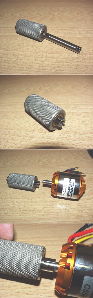
Really? I just drill a hole in the motor shaft and put a roll pin in it. Here's a photo. Doesn't show the pin but in the bottom one you can see where it would go.

5163409587_ec64ea6b91_b.jpg


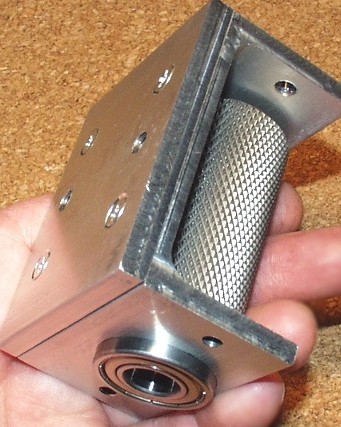
As for a picture. Yup, it's an old picture but same old drive I've been making. That top plate doesn't slide, it's to stiffen the small channel aluminum I was using.

5163397801_cd6988e6ac.jpg


adrian_sm said:
I would be really interested to see what sort of drag your "plain ol' friction drive" has. If it spins down faster than a hub, then personally I would probably just stick with a light weight hub instead. The fact that the variable pressure systems can totally disengage is the only reason I was keen to try it, and the only reason I would put up with some of the down sides of friction drive.

You have a good point about being able to totally disengage the motor. I think you missed the part of my post that said I'm still using a clutch bearing though, so the "plain ol'" version freewheels anyway. I have tried it without and the drag really isn't bad but it would depend on which motor you're using. Never had a hub motor so I can't compare the two.

Don't get me wrong. I'm still using the sliding mount on my main bike. That roller would slip like crazy if I didn't. I'm just talking about low power "assist" type systems.

I think your drive is turning out great btw.


Where did you get your Knurled Friction Drive Rollers with Clutch Bearing? I have been searching for sometime, and can't find anywhere.

Thanks
 
adrian_sm said:
When I say via geometry, I don't mean locking the drive to a position, and hence fixed losses.
I am still talking about a free to pivot progressive contact pressure just like your design, with the motor torque dicatating the contact pressure. I just want to limit the maximum engagement via a deadstop so I can stop too much contact pressure. I think you acheive the same thing but by using a soft-stop, ie. your foam dampener. This applies more and more reaction force as the drive engages, until a balance is found. I was think of a more defined stop to limit excess contact pressure, and hence losses.

Here is a pic of where my motor sits.
Friction Drive Geometry - pic1.PNG
Friction Drive Geometry - pic2.PNG

[...]

Does that make it any clearer ? Or am I just confusing myself, and everyone.

- Adrian

Hello Adrian!
Thanks for your great work! And another special thanks for the documentation!!! I'm very interested in building something very similar and I've done the basics already. I'm still in heavy development and my current topic is keeping contact between motor and tire. Since my motor sometimes runs trough the tire and hits the frame from the upper side I surely need endstops (my wheel is a little loose and my swing arm is PLA, so not very stiff).
However, I've redone some of your geometry work to help judge how the drive should be located and I thought you may be still interested. As soon as this model works for me I am planning to move the motor below the crank as you did and then I am going to redo that, but maybe you are still interested in what I learned.
Here is my first approach to the swing arm geometry.

Thanks again for your effort and sharing mentality! :thumb:
 
hi i made a nice setup that work awesome on a straight road, can reach up to 50km/hrs, also on hills no more than 15% can reach up to 33km/hr with pedal help. the problem its on high angle hills, there is no way for it to work, i have to change shifts on the bike an end up pedaling all the way up with almost no help of the motor an really slow.

have a:
Flipsky FSESC Mini V4 rated 50A
TURNIGY AERODRIVE SK3 - 6374-192KV MOTOR OUTRUNNER rated 80A
An a hailong 48v 12.8ah with BMS rated as 30A continuos discharge. made of lg mh1 3200mah, 13s4p

an running on FOC mode
set 80a on motor
an 30a on battery

any idea what could a change to improve the uphill performance?
(its ugly as hell , but it works :p)
[youtube]https://www.youtube.com/watch?v=381T4H5lJiI[/youtube]
 
Back
Top