250w hub motor scooter mod log

Got a bit of time in the garage today, so I continued working on the rear caliper bracket. All that is left is to do a bit more grinding to make it prettier, and to zap it onto the frame. I was looking at the Y harness I made for the batteries and am really not satisfied. The 10ga wire I bought for the harness is a bit thick and has trouble going into the anderson housing. A few of the andersons have backed out a bit and are already showing signs of pitting from arching. So, I decided to order 30 pairs of xt60 plugs from ebay for cheap! The dimensions are a bit shorter than the andersons, so I'm thinking they will save me some room under the deck and also make it easier to route the left battery leads in a U shape (this battery faces the opposite direction to make more room under the deck). Hopefully those come soon, I'll keep using the andersons until then. It's looking really good for having disc brakes by next weekend. The last test ride was so sketchy-no deck, controllers hanging out, one grip, no brakes, loose front end, yeah I was determined. This weekend has been huge for this project, wish I ad more 4 day weekends. Anyway, as always I'll be back with more progress pics and updates.

xt60 connectors:

http://www.ebay.com/itm/111836192016?_trksid=p2057872.m2749.l2649&ssPageName=STRK%3AMEBIDX%3AIT
 
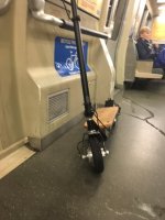
Your speeds are about what I would expect. The only way you are going to get those hub motors rolling faster is more voltage which will get you a bit more or do a complete motor rewind. I know space is limited on your kick scooter, but you have access to machining tools to make custom parts. Consider going back to an unpowered front wheel. Build a bracket for an inrunner or outrunner on the back wheel with a small belt or chain. You will free up a lot of internal space for more batteries since there will only be one speed controller and you wont have to worry about motors fighting each other. You have lots of room over the back wheel to build a bracket for an external motor. I think you are better off in the long run with a single motor rather than 2 motors. Also, a non-hub style motor allows you to mess with gear ratios. If you get an inrunner, they tend to run at high RPM's so that means a pretty small sprocket on the motor and a large one at the wheel. you can totally play with the gearing ratio so that your top speed is 30+ mph. Outrunners tend to be the most efficient since the magnets spin outside the coils rather than inside the coils. This also helps keep the magnets cool. Heat is a real killer for magnets. You will be able to find an outrunner that does everything you want for a reasonable price on HK and elsewhere. All brushless motors have a Kv rating. Get one that can deliver the watts you need plus a little and then look for the one with the highest Kv. That effectively translates into RPM's per volt. With any brushless motor, they tend to run more efficiently at higher RPM's than lower RPM's so going for a high Kv motor just means you need to gear it down more for the wheel speed you want. The idea is you spend most of your riding time cruising around, not taking off from a dead stop. Also gearing down all those RPM's means more torque at the wheel.

On the subject of your hub motors, have you tried taking one of them apart yet? Replace the feild wires with the largest silicon wires you can cram in there. I have noticed that a lot of Chinese motors have low grade wire going into the hub. More strands in the cable means lower wire resistance and more current handling ability. AS you know silicon wire has hair fine strands in the cable. Electrons travel best on the surface of the wire strands so more strands is better. Also, while you have them apart, add halls. :):):) You will also be able to see how the motor is wound. It is not uncommon for motors to have multiple wire strands per field and that the wires are not wrapped very tightly. Many small strands gives you decent current handling and are easier to wind than a single large strand. Each strand is generating its own magnetic feild and multiple strands per feild creates multiple magnetic feilds that may interfere with each other and make the motor less efficient. A single large strand per winding which is much harder to wrap since it is stiffer but is the best way to wind a motor. Look at AstroFlight motors. They are all single strand windings per field. You can buy the wire and rewind your hubs for more RPM's. You will likely get more torque too. I have seen many threads on here and elsewhere for building up brushless motor windings. You can find out how to do it easily enough.

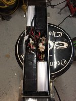
If you get a chance, take apart one of the Lyen controllers and post some close-up pics of the circuit board inside. There is going to be a single square IC mounted on it with pins coming out of all 4 sides. Let me know the numbers on that part. I can find out pretty easily what pin you will need to detach from the rest of the circuit board and is the clock signal. getting both your controller IC's in sync is as easy as disconnecting the clock signal on one board and running a wire from the other controller to the one with the disconnected clock. If you can do some minor soldering on small electronic parts, then you can handle this.

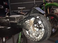
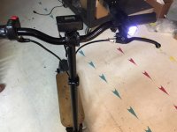
That rear rotor looks great. For the light weight build you are doing those mechanical calipers will work pretty well. I had them on my scooter until I went hydraulic. I'm still using the exact same pad for braking, but I get 80% more braking power out of the hydraulic than the mechanical calipers. My scooter is close to 100 pounds so I'm stopping lots more weight. One thing to watch out for is your brakes will drift out of adjustment slowly over a few weeks time. The pads wear, the cable stretches or slips a little in its clamp...whatever. You want crisp breaking where they are creating no rolling resistance or if needed tons of rolling resistance when you need to stop fast. As things drift out of adjustment, you will find you need to squeeze harder on the levers and the lever travel will grow longer to get stopped. I found that at even 15mph this was disconcerting if I needed to stop fast. I nearly got into a collision with a car because my brakes had drifted out of adjustment. That was after 6 months of constantly adjusting my brakes every couple of weeks. I had gotten complacent and hadn't kept on top of the mechanical brakes. Hydraulic brakes dont suffer from drifting out of adjustment. You may want to look at bicycle hydraulic brakes. The brake lines are the same size as your brake cables and I bet that they would work super well for your kick scooter. I'm looking into using the hydraulic lines on my scooter. Bicycle calipers are probably too light weight for my purposes. There's companies like JagWire that specialize in the fittings and hose part and don't charge a lot for their parts. You can find all the JagWire product line on ebay. Calipers are made by just about every major bike part company. I'm sure you can find something that will suit your design needs really well and weigh half as much as those mechanical brakes and will never give you any trouble.

Regarding XT60 connectors. I know everyone says they are rated for 60 amps. That's pushing it. OK 60 amps momentarily, but continuous and they will overheat. They do fine for 40-50 amps continuous. If that's inside your current handling range, then they will work well. Otherwise go with XT90's or individual bullet connectors. An XT connector is just 2 bullet connectors held together with some plastic and is keyed. When you solder wires to the connectors, have the other gender connector plugged into it. I found that the heat from soldering tends to soften the plastic and allows the pin to wallow out the plastic a little. Having the other gender plugged in keeps things centered up and unmovable until things cool down again.

You mentioned arcing and pitting on your anderson connectors. I assume you mean you get a spark when you connect the batteries to your controller. That is not uncommon and there is a super easy fix for it. The spark is caused by the large electrolytic capacitors inside the speed controller drawing a lot of current momentarily while they charge up. This is commonly referred to as "inrush current". You want to eliminate inrush current for multiple reasons. The biggest one is you are slowly damaging your speed controllers. Secondly is your connectors will be all scarred and useless after a while and need to be cleaned or replaced. The answer to eliminating inrush is simple, but you will need to connect +v and ground separately from each other or have 2 separate power connectors. One power connector will be very small and light weight and needs to handle maybe 1 or 2 amps. The second power connector will be the main current handler. Since I am using 2 8mm bullets for my power connections, I connect the ground wire together. I have a small wire off of my main +V 8mm connector with a 3mm bullet connector on it. It runs in parallel with the main +V bullet connector. On one end is a 5 watt 2K resistor. When I connect the two small bullet connectors voltage is going to the speed controller, but the current is greatly reduced so the capacitors charge slower. I completely eliminate all the inrush current and the arcing issue. By the time you have the small connector connected and you have your hands on the main +V power connection, the capacitors are already charged and you wont get any arcing or inrush. Here's a simple schematic to follow for clarity. If you see some arcing in the small connector use a 10K, 5 watt resistor instead. The capacitors will still charge up quickly.

Sorry for the sloppy drawings. It's 4am...LOL!
Inrush%20circuit%20-%20my%20setup_zpsxzgj1cfq.png


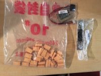
For this one use something like these parts for the small connection.
http://www.ebay.com/itm/5pair-12V-5-5x2-1mm-Male-Female-DC-Power-Socket-Jack-Connector-Cable-Plug-Wire-/262131949455?hash=item3d08481f8f:g:0IUAAOSwgyxWVU3l
Inrush%20circuit%20-%202%20connectors_zpsnbtjbvw2.png
 
Have you seen these? They are a 3-way XT60 connector. This would be perfect for motor fields in your scale of power usage.

http://www.ebay.com/itm/271996577750?_trksid=p2055119.m1438.l2649&ssPageName=STRK%3AMEBIDX%3AIT
 
I just heard from lyen and asked about the best solution to sync the motors, we'll see what he says. I really don't want to mess with SMT stuff, especially the brain of the controller. The motors already have halls. The phase wires are a bit thin, but I'll worry about that later, I want to ride this damn thing! After its all together and I get board with a 24 mph top speed, I may look into rewinding the motors. I'd like to keep both motors on this scooter and not go with an rc setup. I think 2 hubs makes this scooter unique and it will be cool to add to the collection. I've done an rc setup in the past that I added halls to and it was quite a bit of trouble, but really light and fast, I may go that route with my next scooter.

A precharge resistor wouldn't be a bad idea especially right now because I'm connecting and disconnecting the power leads quite a bit. I really like the xt60 connectors you posted I will definitely make the switch when I get the electronics sorted.

I'll keep you posted on what lyen says.
 
I'm working on several precharge ideas. A lot of people are using a loop key as a contactor switch. I'm going to start doing that too. High current (100 amps or more) contactor switches are pretty huge. I know people are getting significant arcing when they plug in their loop keys. The easy and simple solution is just solder a 10K 5W resistor across the loop key pins. This allows a little current to always be getting to the controller to keep those large electrolytic caps charged. At 72 volts that's just 7.2mA. At 48 volts its 4.8ma. It's hardly a noticeable loss. I was working on another simple idea that slow charges the capacitors last night. You use 2 loop keys. One is low wattage and the other is the current carrier. The low wattage loop key could simply have a 1K 5W resistor across its 2 pins. You plug it in first and then a second later plug in the main loop key. I also thought about how much I like indicator lights on things and came up with a super simple LED circuit. You need a current limiting resistor that reduces the voltage across the LED to 3 volts. At 48 volts, that's a 2.7k resistor. Then you run a bunch of LEDs in parallel since a single LED draws maybe 20mA. It takes 20 seconds with 15 LEDs in parallel to charge my caps. I have a couple of LED bulbs that have 5 hi intensity LEDs in them to get 15 watts. The 110v AC to 15v DC converter boards have died, but the LEDs are still good. I'm going to try those LEDs since they draw a lot more current. What's happening in the back ground is initially the caps are discharged. In my case that means a 48 volt differential between the battery level and the capacitors discharged level. The LEDs as a result glow at full brightness when you first plug in the loop key. As the caps charge the LEDs get dimmer and dimmer until the voltage differential between BATT+ and Cap+ is less than 3 volts. At that point the LEDS stop glowing since they no longer have sufficient forward bias. That's close enough to fully charged to eliminate 99.9% of all arcing when you plug in the main loop key. Last night I was using 20mA LEDs so it took 15 of them to get the charge cycle to not be overly long. That and it makes for a bulky charging loop key. I think with 5 high current LEDs, I can limit that to 5 seconds or so for fully charged. Truthfully if you get past the initial inrush (60% charged), then arcing is almost completely gone. Anyway, the LEDs act as the current path to charge the electrolytic caps and they stay lit until the caps are charged or until you plug in the main loop key. The whole thing could be buried in hot glue or clear silicon.
 
Pretty sweet EG, looks like you've been busy. I received my watt meter and high current shunt. The meter is pretty small which is fine and the shunt is huge lol. I also received the xt60 connectors and they're smaller than I was expecting. So I went ahead and ordered 20 pairs of xt90s, I should be happy with those. I will use the xt60s for my other projects.

I've been super busy at work but have made some progress.Last week I rode my hoverboard to lyen's place and dropped off my controller to get repaired. He just messaged me today saying that it is done. He had to replace one of the voltage regulators and has shipped it to me, I should receive it monday. I'll definitely take my time hooking everything up. I'm also going to experiment with adding a 5K potentiometer on the signal wire of the slower spinning motor. I will try and sync both motors that way.

My goal for the weekend is to try and get this thing going on 1 or 2 motors. I have some frame work to do and I still need to weld the brake mount on and cut the line to size. Hopefully I can get some time in the garage this weekend and get this thing going. I'd really like to start commuting on this thing again because I'm getting tired of the hoverboard. I'll be back with more updates.
 

Attachments

  • image1 (31).JPG
    image1 (31).JPG
    48.3 KB · Views: 5,377
Now you know why I use 8mm bullets for power. XT90's are a good bit bigger than xt60's. I use XT60's for individual battery packs, but for main power, I want lots more. This ought to help...

XT6020vs20XT90203_zps6bkhklth.jpg

XT6020vs20XT90201_zpsr99f5tfp.jpg


XT60 bullets are 3mm, XT90 are 5mm...or t least that's what I remember...but could be wrong.
 
EG I got my 90s in today and yes they are quite a bit bigger. I will run the andersons for a few more weeks then I will make the switch to the xt90s.

I was able to get quite a bit done today. I welded the brake mount up and cut the cable to length. The wheel spins pretty nice with little runout. The brakes are very responsive and are a nice upgrade from the drum brakes that the scooter came with. I did a bit of grinding (welds) in the frame and taped up the lipos. I like to add an extra layer of protection to the packs I buy since they aren't hard case packs. I did a bit of rearranging in the battery box and found a better configuration for everything leaving more room and less mess. I hooked up the rear motor and took it for a spin down the street. It felt pretty fast to me, maybe because I've been riding the hoverboard for the past few weeks. I really can't wait to get the front motor hooked up and feel that acceleration. I need to get longer deck screws because of the extensions I added to the battery box. The plan is to take it to work on monday and install the 2nd controller when it comes in. I will slowly add the new parts and fix what needs fixing. Hopefully I have more spare time in the upcoming weeks so I can get this thing done and ready for paint or powder coat.
 

Attachments

  • image6.JPG
    image6.JPG
    54.3 KB · Views: 5,363
  • image7.JPG
    image7.JPG
    73.5 KB · Views: 5,363
How are your motor controllers doing? They are packed in there pretty tight with no air flow or a way to lose heat. Same for the batteries...they must get pretty warm too cooking next the the speed controllers.
 
EG, it is a bit cramped in the battery box, I'm doing my best to make more space. The controllers stay cool, but the batteries warm up a bit because of the 70 amp loads on 10C (yeah right) packs. I have a few vents in the front of the tray, but may need a few more. I may also look into getting a fan in there just to circulate the air.

I started commuting with my scooter again this week. I finally got the controller back from lyen today and hooked it up at my desk at work lol. I forgot how fast this thing is with two motors. I complained about motor noise after my first test ride, but now I like it a lot. The motors sound so cool spooling up, you can hear each one and it's awesome! There is still so much to do to get this thing done, but I kinda like that. If I were riding around a finished scooter I'd probably be a bit bored. I do need to get some paint on this thing because it's starting to rust, today it was POURING and I got water everywhere. The deck needs to be remade and a larger notch needs to be added to the bottom to add some wiggle room for foam. There is also a gap in the front because the deck deck sits higher (the angle of the down tube caused this). I'd like to take care of the new deck and new harnesses this week/weekend. I'm going to make everything as short as possible to make more room and cut down on inductance. I'm also considering using 14ga wire for the charge leads because I only charge at 3 amps or so, that will make it easier to solder two wires to one connector. Another thing I will try and finish wiring the watt meter. Hopefully I can make lots of progress now that I have everything in the battery tray, that was holding up progress. Until then I'm just going to enjoy ripping around in this thing because it's too much fun. I'll be back with more updates.
 

Attachments

  • image1 (4).JPG
    image1 (4).JPG
    57 KB · Views: 5,335
shortcircuit911 said:
EG, it is a bit cramped in the battery box, I'm doing my best to make more space. The controllers stay cool, but the batteries warm up a bit because of the 70 amp loads on 10C (yeah right) packs. I have a few vents in the front of the tray, but may need a few more. I may also look into getting a fan in there just to circulate the air.

I started commuting with my scooter again this week. I finally got the controller back from lyen today and hooked it up at my desk at work lol. I forgot how fast this thing is with two motors. I complained about motor noise after my first test ride, but now I like it a lot. The motors sound so cool spooling up, you can hear each one and it's awesome! There is still so much to do to get this thing done, but I kinda like that. If I were riding around a finished scooter I'd probably be a bit bored. I do need to get some paint on this thing because it's starting to rust, today it was POURING and I got water everywhere. The deck needs to be remade and a larger notch needs to be added to the bottom to add some wiggle room for foam. There is also a gap in the front because the deck deck sits higher (the angle of the down tube caused this). I'd like to take care of the new deck and new harnesses this week/weekend. I'm going to make everything as short as possible to make more room and cut down on inductance. I'm also considering using 14ga wire for the charge leads because I only charge at 3 amps or so, that will make it easier to solder two wires to one connector. Another thing I will try and finish wiring the watt meter. Hopefully I can make lots of progress now that I have everything in the battery tray, that was holding up progress. Until then I'm just going to enjoy ripping around in this thing because it's too much fun. I'll be back with more updates.


Water in your battery/controller bay is a bad thing. Seal it up as best you can and mount your controllers so they can dump heat via the metal box. I had water problems and it caused me lots of issues. Water got into the throttle connector and I had one hell of a time keeping the scooter stopped when sitting at a light during a rain storm. I had water get into my battery packs, but fortunately nothing was harmed. It's just best to not have water intrusion issues. After that, I sealed up every hole and crack I could find. It's finally clearing up here too...time to get riding again!!!
 
Ya I'm working on dealing up the battery box. A huge part of it is making a longer deck. The other holes will get grommets when I finish running all the wiring. Had a few motor hiccups yesterday going over bumps. When I got home I check the motor connections and ended up replacing two hall sensor wire pins and realigned the Anderson plugs (middle housing was backed out a bit). Got off the train this morning and let it rip, the side walk was wet so I ended up doing a double burnout 8) . On my way back to the train just now a woman in a parked car opened her door right in front of me I quickly swung my hips to the left and leaned the scooter out of the way of the door. As I looked back to thank her for looking for people in the bike lane I noticed she was on the phone and oblivious to what just happened. Luckily I was able to dodge that bullet because I don't like to wear helmets (I know, I'm an idiot). Anyway I'll be back with more progress.
 
Be careful out there. I have a friend that rode an electric scooter as a commuter. He was paranoid already and was geared up with a helmet, wrist guards and everything. Just like you, a lady opened up a door right in front of him. Only he hit the door hard as he skidded to a stop. frocked up his leg. Cops got involved, lady had no insurance and eventually got her license suspended. But his lawyer said it wasn't worth a suit to collect damages.

Now he walks everywhere.
 
Crazy man. I was really fortunate I didn't get hurt the other day. All I can do is ride like nobody can see me and get some lights. I've been meaning to get a nice head light for the bars but haven't yet, that might be something I do this weekend.

So yesterday after work I went to my company's holiday party in the city. I was pretty excited about taking my scooter because I had to climb some really steep hills to get there. I hopped onto taylor and took it all the way up, and passed by Lyen's house on the way. It was really fun riding in the street with cars and being able to keep up with them/split lanes. I'm pretty pleased with the way my scooter performed in the city. The streets are far from smooth and they were wet, so it was the ultimate test. My new watt meter is kind of small so it can be tough to see how many watts I'm pulling at full throttle. Up on of the hills I was pulling 70 amps, and somewhere near 2,000 watts, I can't imagine my batteries were too happy pulling that current for 20 sec or so. Going down some of the hills was a bit scary. On one in particular I had a bit or speed at the top and when I went down the brakes weren't super helpful. At one point I was doing about 10 mph with the rear wheel locked up, perhaps front brakes wouldn't be a bad idea. All in all it was a fun night riding around, I'll have to do more excursions in the city soon. I took a few pics, hopefully you can see how steep some of the hills were (it was getting dark).
 

Attachments

  • image1 (1).JPG
    image1 (1).JPG
    58.3 KB · Views: 5,281
  • image2 (1).JPG
    image2 (1).JPG
    54.7 KB · Views: 5,281
Thanks Torque! It's true man drivers in SF DGAF! I don't know how you guys do it on skateboards, you're braver than I am.

EG, I'm working on it. Friday was a reminder that I need more braking power. I will also start playing with the regen soon, hopefully the multistars can take it. Also, I just bought a project enclosure for my watt meter from radioshack, I will try and get it cut up and mounted tomorrow, I'll post pics then.

So my scooter was at 46v today, and after a few PM's with EG I needed to drain my lipos down to my lvc to teach the meter what 0% battery is. So I hammered the throttle everywhere! I probably did a good 5 mile trek on bike trails and around the park by my house. I had the opportunity to climp some steep paved trails and the scooter handled beautifully. It was pulling about 1,700-1,800w going up the big hills. The max current on each controller must be set to 35A (probably because the traces aren't beefed up yet) because I can only pull 70A. I'm so surprised how efficient this thing is. I was playing with different speeds on flat ground and I was only pulling a few amps. If I really wanted to get extra range out of this thing I could turn down the current and just cruise everywhere, but that's no fun. When I got home I checked the temp of the motors and they weren't really even warm to be honest. I pulled the deck and checked the controllers and they we barely warm, the lipos on the other hand were pretty warm. I let them sit for a few hours after I checked them. My scooter's been charging for the past couple hours, just waiting for it to top off so I can set the 100% mark on the watt meter. I still need to get the charging harnesses done and mounted externally so charging will be a breeze. After that, I'll work on the deck and cleaning up the wiring so more.
 
It's like 70% of your braking comes from the front brakes.

I wrapped my watt meter in kapton tape. It wont hold up to imersion, but it keeps the rain out.
 
Yup, I mainly use my front brakes on my motorcycles, will definitely get them hooked up on my scooter soon.

I made a little progress today. I bought a project enclosure from radio shack and milled a section out so I could mount my watt meter in there. It was pretty simple to do, I also wrapped the meter in kapton tape (thanks EG) before installing it. The box is sealed with hot glue so it should do nicely in the rain. I went to the hardware store at work today and noticed I had a flat front tire, that is going to suck to change. It looks like I need to pull the motor apart just to change the tube. Luckily I have spares, so I can do it this weekend. I will also throw the stock front tire on there, the tires that came with the motors are pretty square and are tough, the stock tires have more of an apex and are springier. I'll keep you guys updated as usual.
 

Attachments

  • image1 (2).JPG
    image1 (2).JPG
    41.9 KB · Views: 5,226
shortcircuit911 said:
Yup, I mainly use my front brakes on my motorcycles, will definitely get them hooked up on my scooter soon.

I made a little progress today. I bought a project enclosure from radio shack and milled a section out so I could mount my watt meter in there. It was pretty simple to do, I also wrapped the meter in kapton tape (thanks EG) before installing it. The box is sealed with hot glue so it should do nicely in the rain. I went to the hardware store at work today and noticed I had a flat front tire, that is going to suck to change. It looks like I need to pull the motor apart just to change the tube. Luckily I have spares, so I can do it this weekend. I will also throw the stock front tire on there, the tires that came with the motors are pretty square and are tough, the stock tires have more of an apex and are springier. I'll keep you guys updated as usual.

The meter looks great in that box. I might have to do something like that too! What are you going to do for buttons?

For your flat tire, just get some bike tire goop. I forget the real name, but it's green and you can buy it at walmart. Take the schrader valve out and squeeze some of the goop into the tire. Clean out the threads for the valve with a q-tip and then reinstall the valve. You should be able to pump up the tire and immediately ride around for 10-20 minutes to permanently plug the leak. The 4 oz bottle I have says it is good for 2 bike tires, but I have used half of it on 2 bike tires and my scooter back wheel. I think the manufacturer is going for massive overkill by dumping half the bottle into a tire. For your micro-sized tires, use maybe 1/4 of the bottle at most. This stuff is great for punctures from thorns or other small objects. It won't "fix" a cut though.
 
Thanks man. you should get the meter into something protective because it wouldn't take much to damage it. The green stuff you're referring to is called slime. I've used it before and it works well.I just dont want the wheels to have a huge wobble because of that stuff, or if there is a big hole in the tube that stuff gets everywhere and is a pain to clean. Still thinking about what I'm going to do, been commuting on the hoverboard the past few days and it sucks.
 
shortcircuit911 said:
Thanks man. you should get the meter into something protective because it wouldn't take much to damage it. The green stuff you're referring to is called slime. I've used it before and it works well.I just dont want the wheels to have a huge wobble because of that stuff, or if there is a big hole in the tube that stuff gets everywhere and is a pain to clean. Still thinking about what I'm going to do, been commuting on the hoverboard the past few days and it sucks.

Yes the wobble is not good. That's part of why I put just a little bit in the tube and then immediately go for a ride. It distributes throughout the entire tire and then solidifies. There shouldn't be a wobble afterwards.

My meter has 5 or 6 layers of kapton on it, but a box would be lots better.
 
Well I went to add air to the tire to see if it was a small or large leak and noticed the side wall of the tire said "tubeless". So I re positioned the bead on the lip of the rim and aired it back up, problem solved. I finally got my new LED light in the mail the other day and am pretty happy with it. The mount isn't great but it came with 2 18650s and a charger for them. I brought it to work today and it is pretty bright. It's raining in SF today and I always forget to take it easy on the throttle, but I can't help myself. When I got to work I had a rooster tail of water up the back of my right leg, now I remember why I'm supposed to go easy in the rain. Hopefully it dries up so I can take my scooter to check out some of the superbowl stuff they have going on downtown.
 

Attachments

  • image1.JPG
    image1.JPG
    43.8 KB · Views: 5,128
Ha! I completely covered the back wheel so spray couldn't get me.

I did the same thing with a 1000 lumen crossfire. Mine is under the handle bars to keep it "less busy" on top of them.

IMG_20160102_064414_zpstnq5fdib.jpg
 
Nice man.

Well bad news. I ran my pack down to 40v so I could teach the watt meter what low was. I plugged in the balancer and it was throwing an error. I checked the cells and 2 we at 2.xx and 1 was at 1.xx(same pack). I knew the multistars weren't the best, but I definitely thought they'd last longer than this. Not sure what I'm going to do yet. Been up since 4:30am, not s good way to end the day going to bed, hopefully a solution comes to me tonight.
 
Back
Top