ElectricGod
10 MW
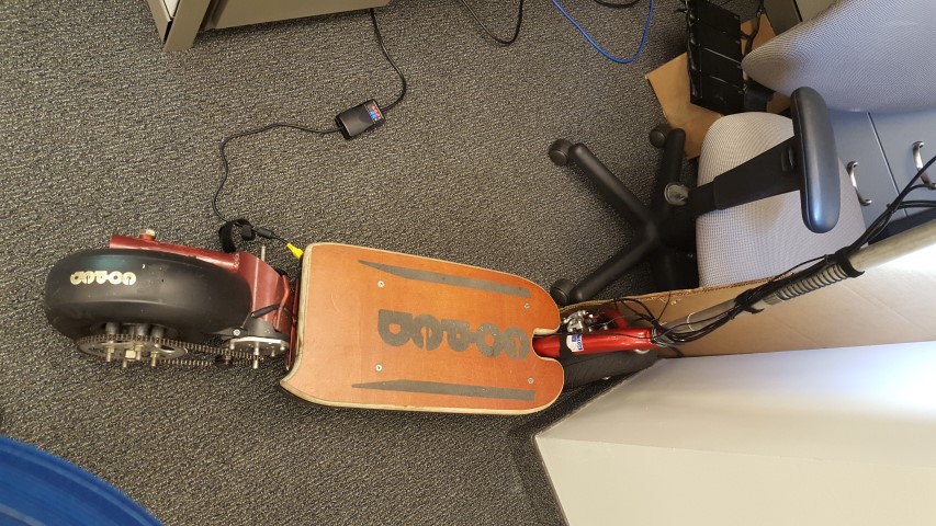
I have a Ford Expedition. As anyone knows they are big and not very conducive for city driving. It's great for hauling people and stuff, but most of the time it's just hauling me back and forth at 18 miles per gallon. I have wanted a better (not gas using) solution for a good while that doesn't require that I sweat everyday going back and forth to work and elsewhere. I have considered gas powered mopeds, but most of the smaller ones are worse polluters than my Expedition for way less engine displacement. I have looked at electric EV devices for a long time, but never found anything that just grabbed me by the short curlies and screamed "BUY ME NOW!!!". I also wanted something that I could modify heavily. Well I kept looking and finally came apon adult sized electric kick scooters. Most of them were pretty lame straight from the factory with 36 volt batteries and maybe a 500 watt motor (Yawn!). I wanted a factory package that was open and easily modified and already could do 30mph or better. I then happened upon HyperPowerSports who sells a wide variety of Chinese adult kick scooters that don't cost you your first born child. I found a model that suited me and then tried to find it elsewhere or to even find reviews for it. It's been since June that I bought mine and I still don't see them sold any where else. I decided to risk it and paid with paypal. I have to say that I have spent $600 on lots of things, but nearly all of them have not given me as much fun and enjoyment as this $600 kick scooter has. It's not perfect from the factory and I'll get to that after a while, but it is mostly made from easily available components that you can find on places like ebay. I bought this model from Rick at HyperPowerSports. Rick and I e-mail 5 or 6 times a week now as I give him updates on what I am doing to his kick scooter.
This is a 48v scooter with a 1500 watt motor. It will legitimately go 30mph with a 240 pound guy riding it right out of the box.

The first thing I noticed when I got the scooter was that overall the build quality was pretty reasonable considering the price I paid for it. The next thing I noticed was after 5 minutes I had already blown the 30 amp fuse. Fortunately, there was an auto parts store right down the street so I bought 40 amp fuses of the same type and I was up and running again. Looking back It seems odd that the speed controller is limited to 40 amps, but the fuse was rated for 30 amps. Of course it was going to blow! I told Rick about this and he told me they are shipping with 40 amp fuses now. At first he looked at me as a troublesome customer because I knew way more than him about all sorts of things and asked lots of questions and nit-picked things, but over time he has come to see me as a resource. Other than the blown fuse, the scooter worked great right out of the box. My drive/ride into work is 10 miles round trip so this scooter was ideal for my purposes. The SLA battery pack weighs about 50 pounds (ugg!) and successfully got me to and from work with conservative riding. If I rode at full throttle (25-30mph) with my 240 pounds on the scooter both ways, the SLA battery was not going to get me home. Well I knew I was going to get rid of the SLA pack before I ever bought the scooter and was already designing LIPO packs.
I bought this BMS and these batteries on ebay to build 48 volt packs out of.
http://www.ebay.com/itm/221274094989?_trksid=p2055119.m1438.l2649&ssPageName=STRK%3AMEBIDX%3AIT
http://www.ebay.com/itm/111720991355?_trksid=p2055119.m1438.l2649&ssPageName=STRK%3AMEBIDX%3AIT
The BMS works, but it does a mediocre job of balancing the cells. It is not uncommon to have cells charging to over 4.2 volts and others getting to 3.9 volts when fully charged. when I built the packs, I added a 6S JST balance connector to each set of 6 cells in the pack for monitoring purposes and for balance charging if needed. Well I have needed to use the balance connectors because the BMS doesn't keep the cells balance charged very well. I still charge the batteries via the BMS, but then I also randomly pull the packs and balance charge them too. Oh well what can you expect for a $40 BMS.
The batteries are cheap LIPO's and as a result didn't last as long as I would like. When they were new with 4 identical 48v packs, I could get 24 miles out of them. 6 months later it's more like 12 miles. They don't list a discharge rating (C rating) in the auction, but the seller claims they are 3C batteries. I doubt it since the solder tabs on the cells are really light weight and probably can't handle 16 amps never mind 24 amps. With 4 packs and the factory speed controller limited to 40 amps, I am never pulling more than 1.5C from any pack anyway so that hasn't been an issue. I ordered 55 of these batteries and got several that were already showing signs of puffing up. I did some basic testing of all the cells to see if they would charge and discharge equally. Any cell that didn't make a minimum cut line got set aside. As a result I had to buy 10 more (grrr!) and 55 was already 7 more cells than I actually needed. Well considering how I was getting them for $9 each, I guess that wasn't so bad. They come with a tiny BMS on each cell so I had to take them off all of the cells. Then I built up packs. Unfortunately I don't have pictures of the pack building process and I'm not about to disassemble one now just for that purpose. I used some high density craft foam I found on ebay to create a thin buffer between each cell and to encapsulate the entire pack to protect it from shocks and jars. Heat in the batteries has never been a problem at the low discharge rates I typically do. Once the packs were all done I used 14awg silicon wires and XT60 connectors to connect them to the electrical system.
I used the factory SLA battery pack less than a week and quickly discovered that the battery connector was inadequate for the job and had overheated and burned out. As a stop gap since I had LIPO packs close to complete and was going to add a proper fuse block and a power distribution block, I replaced it with a DEANS T connector. I'm guessing the factory battery connector was really good for 20 amps...not 40 amps. I told Rick about the battery connector issue, but I don't know if he did anything about them.
Soon after I had 4 LIPO packs ready to go. The below picture is the current state of the battery compartment, but back then it looked quite different. The 4 yellow rectangles are the battery packs. you can see on one of the packs that I have a cell that is failing. I blame the cheap BMS's as the battery balance charges just fine on my LIPO charger. Each pack is 12 lipo cells separated by a 1/16" layer of foam and then wrapped on all 6 sides with more foam and covered in Kapton tape. You can see the balance connectors on each pack. The height of each pack is a perfect fit for the space.

Soon after building the LIPO packs I also installed a 4 way fuse block and a power distribution block designed for power distribution for audio equipment in cars. Both blocks have a plastic cover so it's hard to short something by accident. The fuse block has 4 30 amp fuses and is gold plated. The positive lead off each battery pack has it's own fuse. The power distribution block is rated for 240 amps which is gracious plenty for my purposes. I bought it because it has 1 large screw terminal for 4-8awg wire and 4 smaller screw terminals for 10-16awg wire. It's hard to see in the picture, but the fuse block attaches to the positive side of each battery pack and then goes to an 8 awg wire that goes to the positive side of the terminal block. The negative side of each battery terminates directly into the negative side of the distribution block. Everything is silicon coated wire and either 14 or 8 awg. Coming off the large distribution block is power to the speed controller (8awg) and a 14awg wire set going to the white screw terminal strip. The terminal strip can be disconnected via an XT60 connector. Since a lot of wires are much smaller than 14awg, I needed a way to get power to smaller things than my main power distribution block could handle. I think I paid $2 for that screw terminal strip on ebay and it will take anything 14awg or smaller. Originally all the power distribution was all mounted on the right side of the box, but I recently moved it to the left side to get the speed controller (silver box on right) in.
Soon after installing the LIPO packs (1 month after receiving the scooter) and power distribution I found I was having speed controller problems. At the factory, they hide the speed controller behind a metal plate in the upper section in the above picture. It just sits in there and bakes to death. There is no air flow and the speed controller is mounted with double sided tape to the metal plate. As a result it has no way to dump heat and failed for that reason. Rick sent me a replacement speed controller and I mounted the new controller to the floor of the box and tossed the metal plate. It was still mounted with double sided tape, but it worked fine for 6 months until I got the Kelley Controller (KBS72221E) I am using now. Once I got the replacement controller, I replaced the power wires with 14 awg silicon and terminated them in an XT60. I also noticed that the motor bullet connectors which were good for maybe 10 amps had gotten super hot and fused themselves to various other wires. I had some 3mm RC bullet connectors so I replaced those as well. I ordered some 8mm bullet connectors and now all my motor field and power connections are made up of these.
Here's the 8mm bullet connectors. The shorter ones are fine for the motor feilds, but I wanted maximum current flow for the speed controller power wires so I used these longer and more expensive ones for that. Castle Creations claims the smaller ones are good for 300 amps. I am doubtful, but I'm willing to use them for around 100 amps. The longer ones I would risk up to 150 amps. More than that and I'm going with duplicate connectors!
http://www.ebay.com/itm/400896508745?_trksid=p2057872.m2749.l2649&var=670439394467&ssPageName=STRK%3AMEBIDX%3AIT
http://www.ebay.com/itm/231536147191?_trksid=p2057872.m2749.l2649&ssPageName=STRK%3AMEBIDX%3AIT

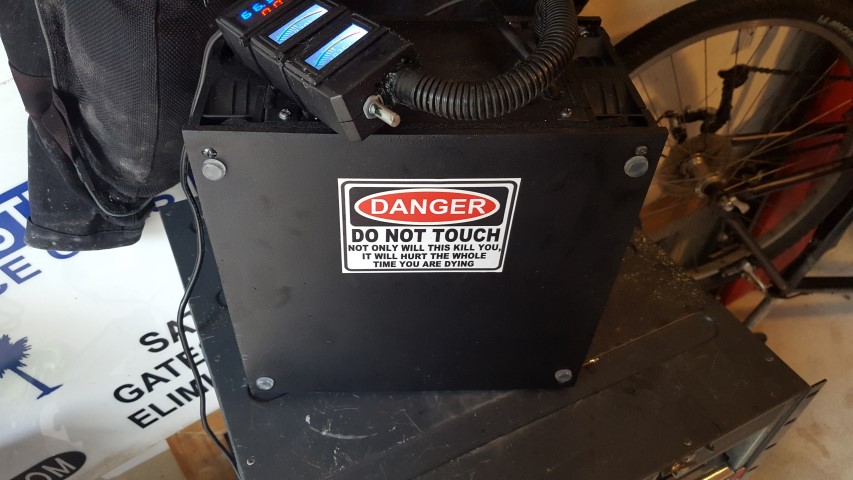
The scooter comes with a 3 LED "meter" on the throttle (ugg!) which I found to be completely inadequate for monitoring anything. Hunting on ebay I found this meter and also purchased a 100 amp shunt. The meter comes with a 50 amp shunt, but it can measure far more current than that. Looking back 100 amps seemed like tons of current, but now I wish I had bought a 200 amp shunt. This little meter is quite small. The top 2 buttons are basically "zero" buttons and there is a simple configuration menu inside too via the bottom button.
http://www.ebay.com/itm/131630345531?_trksid=p2057872.m2749.l2649&ssPageName=STRK%3AMEBIDX%3AIT
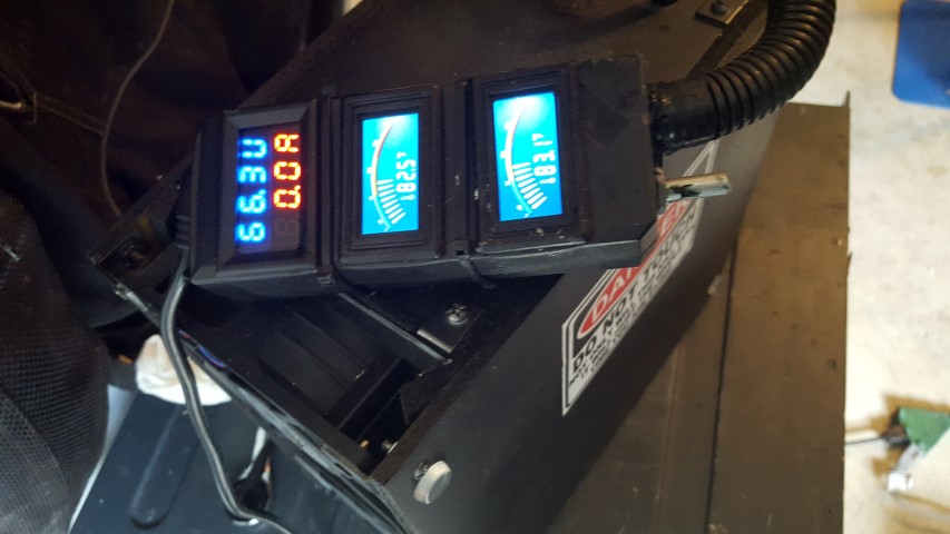
Here's the watt meter and my speedo. I encapsulated the watt meter in Kapton tape so it can't get wet. It has worked pretty well so far and I have ridden in the rain a few times. The buttons are slightly raised from the top surface of the meter so they have Kapton over them too and it doesn't effect them working. This is a great little meter. One thing you have to do is run your batteries down to whatever your discharged level is and then hold down the middle button so it "learns" what 0% is. The top button you use to "learn" 100%. Charge the batteries to full and press the button until it resets to 100%. Until you do both of those things the meter doesn't display the capacity correctly and the battery bar graph works oddly too. Momentarily pushing any button turns on the back light for 5 seconds.

Here's the bike speedo I bought on ebay ($12). It's, wired and water proof and the back light will stay on by holding the "mode" button for 5 seconds. Once you stop moving for a few minutes, the speedo goes to sleep and shuts off the light. I tried several wireless speedo's, but motor or speed controller RF noise kept interfering with them and so they were unreliable.
http://www.ebay.com/itm/351403027972?_trksid=p2057872.m2749.l2649&var=620499609749&ssPageName=STRK%3AMEBIDX%3AIT
Since I only needed a little over 10 miles of battery run time to get to work and home and I had 24 miles of range, I decided more lights was a good idea. The factory lights are not wonderful anyway. I still use them, but they have been supplemented a lot. I have added these items to the factory lights.
This is a great little LED flasher module. It uses 2 relays to flash the LEDs rather than a bimetal strip like most cars have. The low current of LEDs wont heat the bimetal flashers so this is a much better choice. It also has a hazard lights mode.
http://www.ebay.com/itm/361427943219?_trksid=p2057872.m2749.l2649&ssPageName=STRK%3AMEBIDX%3AIT
I have 2 sets of side lights. The white lights are on a switch for the left thumb and the blue lights are on a switch on the throttle.
http://www.ebay.com/itm/401015048819?_trksid=p2057872.m2749.l2649&ssPageName=STRK%3AMEBIDX%3AIT
and
http://www.ebay.com/itm/111327078830?_trksid=p2057872.m2749.l2649&ssPageName=STRK%3AMEBIDX%3AIT
Here's the rear side lights on the scooter. The blue lights are attached to the sides of the battery box. At night I am VERY visible from the side! The light in the second picture is just the long section of the LED strip. The other section is attached to my directional lights.


In the middle of this picture is the original tail light module. The LEDs were OK, but I replaced them with higher intensity LEDs and then added 4 more. I'm probably 50% brighter in back now. I had a couple of bike LED flashers and added them too, but I never turn them on anymore now that the tail light is so bright.
This is the headlight I bought. There are cheaper versions of the same thing with an external power converter module that isn't weather resistant. This one has the power module internal and is weather resistant and quite bright. It will run on anything between 12v and 90v DC with no loss of brightness.
http://www.ebay.com/itm/321710537166?_trksid=p2057872.m2749.l2649&var=510612622147&ssPageName=STRK%3AMEBIDX%3AIT
The light on the left is the ebay light. It's hard to see in the over exposed picture, but it's easily 4X brighter than the factor LED headlight.

Here's my throttle and switch modules. The switch module works fine as it comes from the seller, but I rewired everything and made the cable longer and used an 8 conductor cable so I could use the factory switch as well all off the same cable. The factory throttle was a basic twist style throttle with no extra switches on it. I wanted another control on the right side and didn't like the twist throttle anyway so I bought this thumb throttle. I can ride with the seat on, but I prefer standing up so I rarely use my seat. Holding a twist throttle steady while standing is not as easy as it sounds. The thumb throttle allows you to hold the grips firmly and still operate the throttle and maintain a steady speed. Also, the new grips I used are not slippery when wet or wearing gloves like the factory grips are.
http://www.ebay.com/itm/271652213597?_trksid=p2057872.m2749.l2649&ssPageName=STRK%3AMEBIDX%3AIT
http://www.ebay.com/itm/141682873650?_trksid=p2057872.m2749.l2649&ssPageName=STRK%3AMEBIDX%3AIT
Here's the throttle on my scooter. The little round button goes to the speedo. The rectangular grey button turns the blue side lights on.
Here's the left switch cluster. The right most switches came with the scooter and turned on the horn and head/tail lights. I swapped the buttons so the green horn button locks down and the light button is momentary. The right horn button turns on the back side lights. The red momentary light button acts like flashing your high beams in your car. Sometimes people don't see you coming or just didn't look before they start pulling out so now I can flash my head lights at them and get there attention. The upper left yellow switch is directionals, followed by the red slider switch for head lights and tail lights and then the green horn switch which actually operates the horn. You can see a blue wire with a smaller black one on top of it. The blue wire has 8 conductors goes down inside the battery box and the black wire connects the factory switch module to the 3 switch module. I've adjusted things a little since I took this picture and now the two switch modules sit right next to each other.

The factory motor controller is a typical cheap Chinese device that barely handles the load it was designed for. I looked up the mosfets it uses and they are rated at exactly the current draw required to run the motor at maximum RPM's...with no extra overhead and that is with 3 of then in parallel per phase. Basically, I was waiting for it to die no matter how cool or hot it was getting. Also, I wanted MORE SPEED AND POWER and there was no way the factory controller was going to give me what I wanted. I looked around and read lots of other peoples stories and went with a Kelly KLS7230S speed controller. Kelly has great e-mail based customer service. They usually respond back within a couple of minutes and they know their products really well. I received the KLS7230S controller which can do 230 amps peak, hooked everything up, put it into learning mode so it could detect my motor and then tried it out. My motor stuttered and jerked, but it did run. There's differences in hall sensors and the cheap Chinese hall sensors in my motor sent out spurious signals that the speed controller was responding to and attempting to adjust the motor fields to as a result. I haven't tried it yet, but I have 3 of these motors (2 1500 watt and 1 2000 watt) and I bought the Kelly recommended hall sensors and put them in one of the 1500w motors to see if that "fixes" the hall sensor problem with the KLS controller. Kelly being the great folks they are sent me a different controller (KBS72221E) at a discount that is more forgiving than the KLS series controllers are. In the above picture of my battery bay is the KBS controller in the upper right area. It is working like a champ so far. On the subject of Kelly motor controllers...you get what you pay for. These things are built tough. I think their specs are accurate if not a little conservative. The KBS controller can't do the current that the KLS can, but still it will probably be plenty enough for my purposes. Later if I get an even bigger motor, I can always go back to the KLS. Either way...Kelly motor controllers are really nice controllers and not overly expensive. I would definitely buy more of them in the future. Everything about these controllers is built to last and be reliable. I have mine bolted to the steel box and there's heat sink grease on the underside of the controller. I doubt heat will be much of an issue.
This is the 2000w motor in a bracket I made for it. The original 1500w motor looks identical and is the same dimensions, but has smaller wires and the field coils inside are smaller. The 1500w motor also has a mounting bracket welded to it. I can feel that I have more power with the 2000w motor. This motor is probably equivalent to an astro flight 3210 motor, but at 1/3rd the cost and a little less efficient. I paid $120 for it.

These scooters have atrocious wiring inside them. There's no distribution buss or common way power or ground gets to things. Wires are just twisted together in a hodge podge manner and then badly wrapped in electrical tape. I wanted to start adding more lights and other things so I got into the wiring and it was literally a shocking mess to say the least. As a result, I ran new cables to just about everything except the key switch. The rear lights now have a dedicated 8 conductor cable for them and the left switch cluster does too. The throttle cable was sufficient for the job so I left it alone and the watt meter already had a dedicated cable for it. One of the problems with the wiring inside these scooters is some things switch on or off the ground wire and other things the +V wire. Well if that's not confusing, then what is!? I changed everything to switch off via the ground wire. The reason why is that way +V goes only to the device being powered and not up the steering tube. The wires going to the actual lights are pretty static and don't move much and are protected. The wires coming out of the battery box and up the steering tube are open and exposed in several places. Having hot wires in places where they could get damaged sounded like a bad idea to me so I used ground switching for everything. Now almost nothing "dangerous" and high voltage is exposed to possible shorting. It meant I had to rewire the tail lights, head lights, horn, switches, etc to all work via ground switching. It was a pain to do, but I think worth the effort.
Because I was rewiring everything anyway, I wanted to use a screw terminal block that everything goes to before it goes elsewhere. I originally used one of those 8 position white blocks, but I needed lots more than 8 screw terminals and it was overkill anyway so I got on ebay and found some smaller ones that were garbage and then found these which are well made. All the wires going from switches to lights or whatever are all small wires (24 to 28 awg) so I don't need a high current screw terminal block. I took these screw terminals and hot glued them back to back and then soldered their pins together to make my own mini terminal strip with 32 positions. Each set of 8 positions was super glued end to end. That left a nice "V" channel down the middle of the whole block so I dropped a long strip of metal in there and hot glued it in for extra strength. I currently have 6 free positions left on it. With the crappy terminal strip I had quite a few wires wire nutted together.
http://www.ebay.com/itm/121656367746?_trksid=p2057872.m2749.l2649&ssPageName=STRK%3AMEBIDX%3AIT
In this picture you can see the old terminal strip made from the garbage parts and the final product behind it. They are almost the same length, but the new one in the back has 32 positions rather than 16 and it's a way better quality terminal block. I doubt I will replace it again because it works so well. 100% of my wires for whatever switch or light or whatever all go into the terminal block now. Each wire hole is pretty small, but it will hold an 18 awg wire or 2 24 awg wires. The terminal block gets stuffed up under the front section of the battery box where all the wires terminate anyway.

I also added a back deck. In the original picture you can see the scooter has a tiny mud cover over the back wheel. It wasn't enough to keep water spray off your back and so I commonly got water and dirt up my back on wet days. I wanted some cargo space anyway or a place to carry a passenger and so the back deck was the perfect solution, fixes the water spray issue and gave me a natural mounting point for all the rear lights. I made it strong enough to carry my 240 pounds, but still be really light. I think it added 3 pounds to the scooter when done. The top is covered in grip tape and I have some threaded brass inserts in it so that I can mount a basket back there too. That grey wire is the cable that runs all the lights in the back. You can't see it, but right below the motor is a weather proof connector that allows me to disconnect all the back end electrical from the scooter if I need to remove the back deck. There's another one right behind the tail light that disconnects the side lights so I can work on the tail light module if needed.
Here it is from behind and from the side.

I found these connectors on ebay in 3 to 8 pin configurations. I use an 8 pin version for the tail section disconnect and a 6 pin connector for the hall wires coming out of the motor. completely assembled, they are about the size of your index finger and water proof. Considering their size and price, they are quite rugged.
http://www.ebay.com/itm/231735605119?_trksid=p2057872.m2749.l2649&var=530946427677&ssPageName=STRK%3AMEBIDX%3AIT

The motor as it came from the factory has a single long cable that terminates inside the battery box. I wanted to be able to swap out motors or to temporarily plug one in for testing or whatever without having to pull everything apart to do it. I ordered some 10 awg silicon wire and put 8mm bullet connectors on both ends and ran it in place of the long cable coming out of the motor. I also ran a separate cable for the hall sensors which terminates onto my terminal strip inside the battery box and into a weather proof connector at the motor.
This is the motor wires tucked in next to the motor. You can see the black hall connector.

This is the original 1500w motor disconnected and pulled out. The motor wires are 8" long and easily disconnect. I wrap each field connection in a little electrical tape since it is possible that water could get into them and possibly cause issues.

Almost done...LOL!
I wanted to have everything run on 12 volts and finding stuff that runs on 48 volts is limited and higher than that is virtually impossible. 12 volt stuff is like trying to find sand at the beach. All the lights and horn originally ran on 48 volts. As long as I never changed my operating voltage from 48 volts that was fine, but I have every intention now that I have a Kelly controller that can handle lots more voltage to upgrade to 72 volts later. That meant I needed a DC-DC converter and I found one on ebay that is good up to 80 volts and converts down to 12 volts at 3 amps. I just needed to run LEDs and the horn so that's plenty of current for my needs. It's a little difficult to see in this picture, but that silver box in the upper right corner is the DC-DC converter. There's a blue 4 screw terminal block to the left of it. That is the 12 volts coming out of the converter. I put my amp meter on the converter and found even with no load it was still pulling several hundred milli-amps (grrr). Well that was no good as it would eventually run down the batteries. Originally the key switch turned off power to all the peripheral items in the scooter, but the Kelley controllers all use 5 volts to enable the controllers so that meant the key switch was now tango uniform for applying power to everything. Originally I mounted a 15 amp toggle switch under the right edge of the deck to turn everything off, but I kept forgetting to flip the switch off when I got to work or to turn it back on when it was time to go home. My solution was to go through my scrounge pile of old power supplies and electronics and find several power mosfets that could be turned on with 5 volts and could handle 10 amps and 80 volts. An hour later I had quite a few that did what I needed. I then picked the best of them and using an old CPU heat sink created a simple mosfet switch using n-channel mosfets. That's the yellow square thing in the picture. It's thoroughly wrapped in Kapton tape. Being they are n-channel mosfets, they switch the ground side of the circuit rather than the positive side of the circuit. That means the ground reference for everything going through the mosfet switch is lost when they are turned off. That meant I needed an isolated ground and 12 volts completely separate from everything else. When you measure across source to drain with the mosfets turned off you get 26 volts and infinite resistance. Keep in mind that there is other stuff (the switched load) in series with the mosfets that are providing some resistance. This why I measured 26 volts rather than 48 volts across the mosfets. Turn them on and you get 0 volts and .03 ohms. Fortunately, ground based switching was easy to do since I had just rewired everything for ground switching. So everything switched on by the mosfets has a separate ground reference from the battery source when the mosfets are turned off. Switched on and the internal resistance of the mosfets is so low that you can't tell they are there and the regular ground reference is restored. It seems like an odd way of doing things, but it works reliably and now power to everything except the speed controller is turned on and off automatically by the key switch and 5 volts. One of the wonderful things about mosfets is they consume so little power to remain activated...a few picoamps since the gate has virtually infinite resistance. Turned off they act just like an open switch and turned on they act like a closed switch. A relay by comparison has mechanical contacts where arcing can occur and they require at least a few milliamps or more to activate. Most 5 volt relays are low current devices anyway and wont have high current contacts. The mosfets are a much better choice. In this picture the gold thing on the left side is my power distribution block.

Here's a better picture of the fuse block and power distribution block.

This is the back wheel taken off. The axle bearings are of marginal quality and I have had to take them apart and re-grease them at least once in the past 6 months even though they are sealed bearings. I'll replace them after a while. This picture is really here because the rear sprocket is on a freewheel. I had to find a castle nut socket that fit the the one-way clutch. It has no seals on it and dirt, water, whatever gets into it pretty easily. I noticed it was making crunching sounds and so I knew that wasn't good.

Here it is taken apart and cleaned up. Fortunately the bearing races were not damaged

It's unfortunate that it has only 2 pawls in it and they are smallish. I expect it will be a breaking point after a while.

And reassembled. I spun it a 20 or 30 times to get the grease redistributed and to see if it sounded OK or not. That white circle is the grease coming back out of the one-way clutch. There's a tiny space in the one-way clutch where I might be able to add a grease nipple or at least a grease fill hole. That way I won't have to take it apart and I can just force grease into it. When I took it apart, it was completely dry inside (no lubricant anywhere)...just grit and some hardened black gunk on everything.

I don't know about anyone else, but after a while I forget things. I needed a single source where everything scooter could be referenced. This is pretty much how everything hooks together electrically. I have added some more stuff since I took this picture so this is a little bit dated. Feel free to "borrow as you see fit".

OK...one last thing. I got tired of spending hours on my knees praying to the scooter god...umm I mean working on the wiring inside the battery box or whatever. There were also times when I needed to run the motor off the ground or to generally test things. I made this stand completely out of scrap wood and random hardware. It cost me electricity to make and that's it. Anyway, the bottom drawer has spare scooter parts in it and the top drawer has some tools in it. The top rotates separate from the base and the base has castors under it so I can roll the whole thing around. It's strong enough to hold my weight and the scooter.

This is a 48v scooter with a 1500 watt motor. It will legitimately go 30mph with a 240 pound guy riding it right out of the box.
The first thing I noticed when I got the scooter was that overall the build quality was pretty reasonable considering the price I paid for it. The next thing I noticed was after 5 minutes I had already blown the 30 amp fuse. Fortunately, there was an auto parts store right down the street so I bought 40 amp fuses of the same type and I was up and running again. Looking back It seems odd that the speed controller is limited to 40 amps, but the fuse was rated for 30 amps. Of course it was going to blow! I told Rick about this and he told me they are shipping with 40 amp fuses now. At first he looked at me as a troublesome customer because I knew way more than him about all sorts of things and asked lots of questions and nit-picked things, but over time he has come to see me as a resource. Other than the blown fuse, the scooter worked great right out of the box. My drive/ride into work is 10 miles round trip so this scooter was ideal for my purposes. The SLA battery pack weighs about 50 pounds (ugg!) and successfully got me to and from work with conservative riding. If I rode at full throttle (25-30mph) with my 240 pounds on the scooter both ways, the SLA battery was not going to get me home. Well I knew I was going to get rid of the SLA pack before I ever bought the scooter and was already designing LIPO packs.
I bought this BMS and these batteries on ebay to build 48 volt packs out of.
http://www.ebay.com/itm/221274094989?_trksid=p2055119.m1438.l2649&ssPageName=STRK%3AMEBIDX%3AIT
http://www.ebay.com/itm/111720991355?_trksid=p2055119.m1438.l2649&ssPageName=STRK%3AMEBIDX%3AIT
The BMS works, but it does a mediocre job of balancing the cells. It is not uncommon to have cells charging to over 4.2 volts and others getting to 3.9 volts when fully charged. when I built the packs, I added a 6S JST balance connector to each set of 6 cells in the pack for monitoring purposes and for balance charging if needed. Well I have needed to use the balance connectors because the BMS doesn't keep the cells balance charged very well. I still charge the batteries via the BMS, but then I also randomly pull the packs and balance charge them too. Oh well what can you expect for a $40 BMS.
The batteries are cheap LIPO's and as a result didn't last as long as I would like. When they were new with 4 identical 48v packs, I could get 24 miles out of them. 6 months later it's more like 12 miles. They don't list a discharge rating (C rating) in the auction, but the seller claims they are 3C batteries. I doubt it since the solder tabs on the cells are really light weight and probably can't handle 16 amps never mind 24 amps. With 4 packs and the factory speed controller limited to 40 amps, I am never pulling more than 1.5C from any pack anyway so that hasn't been an issue. I ordered 55 of these batteries and got several that were already showing signs of puffing up. I did some basic testing of all the cells to see if they would charge and discharge equally. Any cell that didn't make a minimum cut line got set aside. As a result I had to buy 10 more (grrr!) and 55 was already 7 more cells than I actually needed. Well considering how I was getting them for $9 each, I guess that wasn't so bad. They come with a tiny BMS on each cell so I had to take them off all of the cells. Then I built up packs. Unfortunately I don't have pictures of the pack building process and I'm not about to disassemble one now just for that purpose. I used some high density craft foam I found on ebay to create a thin buffer between each cell and to encapsulate the entire pack to protect it from shocks and jars. Heat in the batteries has never been a problem at the low discharge rates I typically do. Once the packs were all done I used 14awg silicon wires and XT60 connectors to connect them to the electrical system.
I used the factory SLA battery pack less than a week and quickly discovered that the battery connector was inadequate for the job and had overheated and burned out. As a stop gap since I had LIPO packs close to complete and was going to add a proper fuse block and a power distribution block, I replaced it with a DEANS T connector. I'm guessing the factory battery connector was really good for 20 amps...not 40 amps. I told Rick about the battery connector issue, but I don't know if he did anything about them.
Soon after I had 4 LIPO packs ready to go. The below picture is the current state of the battery compartment, but back then it looked quite different. The 4 yellow rectangles are the battery packs. you can see on one of the packs that I have a cell that is failing. I blame the cheap BMS's as the battery balance charges just fine on my LIPO charger. Each pack is 12 lipo cells separated by a 1/16" layer of foam and then wrapped on all 6 sides with more foam and covered in Kapton tape. You can see the balance connectors on each pack. The height of each pack is a perfect fit for the space.
Soon after building the LIPO packs I also installed a 4 way fuse block and a power distribution block designed for power distribution for audio equipment in cars. Both blocks have a plastic cover so it's hard to short something by accident. The fuse block has 4 30 amp fuses and is gold plated. The positive lead off each battery pack has it's own fuse. The power distribution block is rated for 240 amps which is gracious plenty for my purposes. I bought it because it has 1 large screw terminal for 4-8awg wire and 4 smaller screw terminals for 10-16awg wire. It's hard to see in the picture, but the fuse block attaches to the positive side of each battery pack and then goes to an 8 awg wire that goes to the positive side of the terminal block. The negative side of each battery terminates directly into the negative side of the distribution block. Everything is silicon coated wire and either 14 or 8 awg. Coming off the large distribution block is power to the speed controller (8awg) and a 14awg wire set going to the white screw terminal strip. The terminal strip can be disconnected via an XT60 connector. Since a lot of wires are much smaller than 14awg, I needed a way to get power to smaller things than my main power distribution block could handle. I think I paid $2 for that screw terminal strip on ebay and it will take anything 14awg or smaller. Originally all the power distribution was all mounted on the right side of the box, but I recently moved it to the left side to get the speed controller (silver box on right) in.
Soon after installing the LIPO packs (1 month after receiving the scooter) and power distribution I found I was having speed controller problems. At the factory, they hide the speed controller behind a metal plate in the upper section in the above picture. It just sits in there and bakes to death. There is no air flow and the speed controller is mounted with double sided tape to the metal plate. As a result it has no way to dump heat and failed for that reason. Rick sent me a replacement speed controller and I mounted the new controller to the floor of the box and tossed the metal plate. It was still mounted with double sided tape, but it worked fine for 6 months until I got the Kelley Controller (KBS72221E) I am using now. Once I got the replacement controller, I replaced the power wires with 14 awg silicon and terminated them in an XT60. I also noticed that the motor bullet connectors which were good for maybe 10 amps had gotten super hot and fused themselves to various other wires. I had some 3mm RC bullet connectors so I replaced those as well. I ordered some 8mm bullet connectors and now all my motor field and power connections are made up of these.
Here's the 8mm bullet connectors. The shorter ones are fine for the motor feilds, but I wanted maximum current flow for the speed controller power wires so I used these longer and more expensive ones for that. Castle Creations claims the smaller ones are good for 300 amps. I am doubtful, but I'm willing to use them for around 100 amps. The longer ones I would risk up to 150 amps. More than that and I'm going with duplicate connectors!
http://www.ebay.com/itm/400896508745?_trksid=p2057872.m2749.l2649&var=670439394467&ssPageName=STRK%3AMEBIDX%3AIT
http://www.ebay.com/itm/231536147191?_trksid=p2057872.m2749.l2649&ssPageName=STRK%3AMEBIDX%3AIT
The scooter comes with a 3 LED "meter" on the throttle (ugg!) which I found to be completely inadequate for monitoring anything. Hunting on ebay I found this meter and also purchased a 100 amp shunt. The meter comes with a 50 amp shunt, but it can measure far more current than that. Looking back 100 amps seemed like tons of current, but now I wish I had bought a 200 amp shunt. This little meter is quite small. The top 2 buttons are basically "zero" buttons and there is a simple configuration menu inside too via the bottom button.
http://www.ebay.com/itm/131630345531?_trksid=p2057872.m2749.l2649&ssPageName=STRK%3AMEBIDX%3AIT
Here's the watt meter and my speedo. I encapsulated the watt meter in Kapton tape so it can't get wet. It has worked pretty well so far and I have ridden in the rain a few times. The buttons are slightly raised from the top surface of the meter so they have Kapton over them too and it doesn't effect them working. This is a great little meter. One thing you have to do is run your batteries down to whatever your discharged level is and then hold down the middle button so it "learns" what 0% is. The top button you use to "learn" 100%. Charge the batteries to full and press the button until it resets to 100%. Until you do both of those things the meter doesn't display the capacity correctly and the battery bar graph works oddly too. Momentarily pushing any button turns on the back light for 5 seconds.
Here's the bike speedo I bought on ebay ($12). It's, wired and water proof and the back light will stay on by holding the "mode" button for 5 seconds. Once you stop moving for a few minutes, the speedo goes to sleep and shuts off the light. I tried several wireless speedo's, but motor or speed controller RF noise kept interfering with them and so they were unreliable.
http://www.ebay.com/itm/351403027972?_trksid=p2057872.m2749.l2649&var=620499609749&ssPageName=STRK%3AMEBIDX%3AIT
Since I only needed a little over 10 miles of battery run time to get to work and home and I had 24 miles of range, I decided more lights was a good idea. The factory lights are not wonderful anyway. I still use them, but they have been supplemented a lot. I have added these items to the factory lights.
This is a great little LED flasher module. It uses 2 relays to flash the LEDs rather than a bimetal strip like most cars have. The low current of LEDs wont heat the bimetal flashers so this is a much better choice. It also has a hazard lights mode.
http://www.ebay.com/itm/361427943219?_trksid=p2057872.m2749.l2649&ssPageName=STRK%3AMEBIDX%3AIT
I have 2 sets of side lights. The white lights are on a switch for the left thumb and the blue lights are on a switch on the throttle.
http://www.ebay.com/itm/401015048819?_trksid=p2057872.m2749.l2649&ssPageName=STRK%3AMEBIDX%3AIT
and
http://www.ebay.com/itm/111327078830?_trksid=p2057872.m2749.l2649&ssPageName=STRK%3AMEBIDX%3AIT
Here's the rear side lights on the scooter. The blue lights are attached to the sides of the battery box. At night I am VERY visible from the side! The light in the second picture is just the long section of the LED strip. The other section is attached to my directional lights.
In the middle of this picture is the original tail light module. The LEDs were OK, but I replaced them with higher intensity LEDs and then added 4 more. I'm probably 50% brighter in back now. I had a couple of bike LED flashers and added them too, but I never turn them on anymore now that the tail light is so bright.
This is the headlight I bought. There are cheaper versions of the same thing with an external power converter module that isn't weather resistant. This one has the power module internal and is weather resistant and quite bright. It will run on anything between 12v and 90v DC with no loss of brightness.
http://www.ebay.com/itm/321710537166?_trksid=p2057872.m2749.l2649&var=510612622147&ssPageName=STRK%3AMEBIDX%3AIT
The light on the left is the ebay light. It's hard to see in the over exposed picture, but it's easily 4X brighter than the factor LED headlight.
Here's my throttle and switch modules. The switch module works fine as it comes from the seller, but I rewired everything and made the cable longer and used an 8 conductor cable so I could use the factory switch as well all off the same cable. The factory throttle was a basic twist style throttle with no extra switches on it. I wanted another control on the right side and didn't like the twist throttle anyway so I bought this thumb throttle. I can ride with the seat on, but I prefer standing up so I rarely use my seat. Holding a twist throttle steady while standing is not as easy as it sounds. The thumb throttle allows you to hold the grips firmly and still operate the throttle and maintain a steady speed. Also, the new grips I used are not slippery when wet or wearing gloves like the factory grips are.
http://www.ebay.com/itm/271652213597?_trksid=p2057872.m2749.l2649&ssPageName=STRK%3AMEBIDX%3AIT
http://www.ebay.com/itm/141682873650?_trksid=p2057872.m2749.l2649&ssPageName=STRK%3AMEBIDX%3AIT
Here's the throttle on my scooter. The little round button goes to the speedo. The rectangular grey button turns the blue side lights on.
Here's the left switch cluster. The right most switches came with the scooter and turned on the horn and head/tail lights. I swapped the buttons so the green horn button locks down and the light button is momentary. The right horn button turns on the back side lights. The red momentary light button acts like flashing your high beams in your car. Sometimes people don't see you coming or just didn't look before they start pulling out so now I can flash my head lights at them and get there attention. The upper left yellow switch is directionals, followed by the red slider switch for head lights and tail lights and then the green horn switch which actually operates the horn. You can see a blue wire with a smaller black one on top of it. The blue wire has 8 conductors goes down inside the battery box and the black wire connects the factory switch module to the 3 switch module. I've adjusted things a little since I took this picture and now the two switch modules sit right next to each other.
The factory motor controller is a typical cheap Chinese device that barely handles the load it was designed for. I looked up the mosfets it uses and they are rated at exactly the current draw required to run the motor at maximum RPM's...with no extra overhead and that is with 3 of then in parallel per phase. Basically, I was waiting for it to die no matter how cool or hot it was getting. Also, I wanted MORE SPEED AND POWER and there was no way the factory controller was going to give me what I wanted. I looked around and read lots of other peoples stories and went with a Kelly KLS7230S speed controller. Kelly has great e-mail based customer service. They usually respond back within a couple of minutes and they know their products really well. I received the KLS7230S controller which can do 230 amps peak, hooked everything up, put it into learning mode so it could detect my motor and then tried it out. My motor stuttered and jerked, but it did run. There's differences in hall sensors and the cheap Chinese hall sensors in my motor sent out spurious signals that the speed controller was responding to and attempting to adjust the motor fields to as a result. I haven't tried it yet, but I have 3 of these motors (2 1500 watt and 1 2000 watt) and I bought the Kelly recommended hall sensors and put them in one of the 1500w motors to see if that "fixes" the hall sensor problem with the KLS controller. Kelly being the great folks they are sent me a different controller (KBS72221E) at a discount that is more forgiving than the KLS series controllers are. In the above picture of my battery bay is the KBS controller in the upper right area. It is working like a champ so far. On the subject of Kelly motor controllers...you get what you pay for. These things are built tough. I think their specs are accurate if not a little conservative. The KBS controller can't do the current that the KLS can, but still it will probably be plenty enough for my purposes. Later if I get an even bigger motor, I can always go back to the KLS. Either way...Kelly motor controllers are really nice controllers and not overly expensive. I would definitely buy more of them in the future. Everything about these controllers is built to last and be reliable. I have mine bolted to the steel box and there's heat sink grease on the underside of the controller. I doubt heat will be much of an issue.
This is the 2000w motor in a bracket I made for it. The original 1500w motor looks identical and is the same dimensions, but has smaller wires and the field coils inside are smaller. The 1500w motor also has a mounting bracket welded to it. I can feel that I have more power with the 2000w motor. This motor is probably equivalent to an astro flight 3210 motor, but at 1/3rd the cost and a little less efficient. I paid $120 for it.
These scooters have atrocious wiring inside them. There's no distribution buss or common way power or ground gets to things. Wires are just twisted together in a hodge podge manner and then badly wrapped in electrical tape. I wanted to start adding more lights and other things so I got into the wiring and it was literally a shocking mess to say the least. As a result, I ran new cables to just about everything except the key switch. The rear lights now have a dedicated 8 conductor cable for them and the left switch cluster does too. The throttle cable was sufficient for the job so I left it alone and the watt meter already had a dedicated cable for it. One of the problems with the wiring inside these scooters is some things switch on or off the ground wire and other things the +V wire. Well if that's not confusing, then what is!? I changed everything to switch off via the ground wire. The reason why is that way +V goes only to the device being powered and not up the steering tube. The wires going to the actual lights are pretty static and don't move much and are protected. The wires coming out of the battery box and up the steering tube are open and exposed in several places. Having hot wires in places where they could get damaged sounded like a bad idea to me so I used ground switching for everything. Now almost nothing "dangerous" and high voltage is exposed to possible shorting. It meant I had to rewire the tail lights, head lights, horn, switches, etc to all work via ground switching. It was a pain to do, but I think worth the effort.
Because I was rewiring everything anyway, I wanted to use a screw terminal block that everything goes to before it goes elsewhere. I originally used one of those 8 position white blocks, but I needed lots more than 8 screw terminals and it was overkill anyway so I got on ebay and found some smaller ones that were garbage and then found these which are well made. All the wires going from switches to lights or whatever are all small wires (24 to 28 awg) so I don't need a high current screw terminal block. I took these screw terminals and hot glued them back to back and then soldered their pins together to make my own mini terminal strip with 32 positions. Each set of 8 positions was super glued end to end. That left a nice "V" channel down the middle of the whole block so I dropped a long strip of metal in there and hot glued it in for extra strength. I currently have 6 free positions left on it. With the crappy terminal strip I had quite a few wires wire nutted together.
http://www.ebay.com/itm/121656367746?_trksid=p2057872.m2749.l2649&ssPageName=STRK%3AMEBIDX%3AIT
In this picture you can see the old terminal strip made from the garbage parts and the final product behind it. They are almost the same length, but the new one in the back has 32 positions rather than 16 and it's a way better quality terminal block. I doubt I will replace it again because it works so well. 100% of my wires for whatever switch or light or whatever all go into the terminal block now. Each wire hole is pretty small, but it will hold an 18 awg wire or 2 24 awg wires. The terminal block gets stuffed up under the front section of the battery box where all the wires terminate anyway.
I also added a back deck. In the original picture you can see the scooter has a tiny mud cover over the back wheel. It wasn't enough to keep water spray off your back and so I commonly got water and dirt up my back on wet days. I wanted some cargo space anyway or a place to carry a passenger and so the back deck was the perfect solution, fixes the water spray issue and gave me a natural mounting point for all the rear lights. I made it strong enough to carry my 240 pounds, but still be really light. I think it added 3 pounds to the scooter when done. The top is covered in grip tape and I have some threaded brass inserts in it so that I can mount a basket back there too. That grey wire is the cable that runs all the lights in the back. You can't see it, but right below the motor is a weather proof connector that allows me to disconnect all the back end electrical from the scooter if I need to remove the back deck. There's another one right behind the tail light that disconnects the side lights so I can work on the tail light module if needed.
Here it is from behind and from the side.
I found these connectors on ebay in 3 to 8 pin configurations. I use an 8 pin version for the tail section disconnect and a 6 pin connector for the hall wires coming out of the motor. completely assembled, they are about the size of your index finger and water proof. Considering their size and price, they are quite rugged.
http://www.ebay.com/itm/231735605119?_trksid=p2057872.m2749.l2649&var=530946427677&ssPageName=STRK%3AMEBIDX%3AIT
The motor as it came from the factory has a single long cable that terminates inside the battery box. I wanted to be able to swap out motors or to temporarily plug one in for testing or whatever without having to pull everything apart to do it. I ordered some 10 awg silicon wire and put 8mm bullet connectors on both ends and ran it in place of the long cable coming out of the motor. I also ran a separate cable for the hall sensors which terminates onto my terminal strip inside the battery box and into a weather proof connector at the motor.
This is the motor wires tucked in next to the motor. You can see the black hall connector.
This is the original 1500w motor disconnected and pulled out. The motor wires are 8" long and easily disconnect. I wrap each field connection in a little electrical tape since it is possible that water could get into them and possibly cause issues.
Almost done...LOL!
I wanted to have everything run on 12 volts and finding stuff that runs on 48 volts is limited and higher than that is virtually impossible. 12 volt stuff is like trying to find sand at the beach. All the lights and horn originally ran on 48 volts. As long as I never changed my operating voltage from 48 volts that was fine, but I have every intention now that I have a Kelly controller that can handle lots more voltage to upgrade to 72 volts later. That meant I needed a DC-DC converter and I found one on ebay that is good up to 80 volts and converts down to 12 volts at 3 amps. I just needed to run LEDs and the horn so that's plenty of current for my needs. It's a little difficult to see in this picture, but that silver box in the upper right corner is the DC-DC converter. There's a blue 4 screw terminal block to the left of it. That is the 12 volts coming out of the converter. I put my amp meter on the converter and found even with no load it was still pulling several hundred milli-amps (grrr). Well that was no good as it would eventually run down the batteries. Originally the key switch turned off power to all the peripheral items in the scooter, but the Kelley controllers all use 5 volts to enable the controllers so that meant the key switch was now tango uniform for applying power to everything. Originally I mounted a 15 amp toggle switch under the right edge of the deck to turn everything off, but I kept forgetting to flip the switch off when I got to work or to turn it back on when it was time to go home. My solution was to go through my scrounge pile of old power supplies and electronics and find several power mosfets that could be turned on with 5 volts and could handle 10 amps and 80 volts. An hour later I had quite a few that did what I needed. I then picked the best of them and using an old CPU heat sink created a simple mosfet switch using n-channel mosfets. That's the yellow square thing in the picture. It's thoroughly wrapped in Kapton tape. Being they are n-channel mosfets, they switch the ground side of the circuit rather than the positive side of the circuit. That means the ground reference for everything going through the mosfet switch is lost when they are turned off. That meant I needed an isolated ground and 12 volts completely separate from everything else. When you measure across source to drain with the mosfets turned off you get 26 volts and infinite resistance. Keep in mind that there is other stuff (the switched load) in series with the mosfets that are providing some resistance. This why I measured 26 volts rather than 48 volts across the mosfets. Turn them on and you get 0 volts and .03 ohms. Fortunately, ground based switching was easy to do since I had just rewired everything for ground switching. So everything switched on by the mosfets has a separate ground reference from the battery source when the mosfets are turned off. Switched on and the internal resistance of the mosfets is so low that you can't tell they are there and the regular ground reference is restored. It seems like an odd way of doing things, but it works reliably and now power to everything except the speed controller is turned on and off automatically by the key switch and 5 volts. One of the wonderful things about mosfets is they consume so little power to remain activated...a few picoamps since the gate has virtually infinite resistance. Turned off they act just like an open switch and turned on they act like a closed switch. A relay by comparison has mechanical contacts where arcing can occur and they require at least a few milliamps or more to activate. Most 5 volt relays are low current devices anyway and wont have high current contacts. The mosfets are a much better choice. In this picture the gold thing on the left side is my power distribution block.
Here's a better picture of the fuse block and power distribution block.
This is the back wheel taken off. The axle bearings are of marginal quality and I have had to take them apart and re-grease them at least once in the past 6 months even though they are sealed bearings. I'll replace them after a while. This picture is really here because the rear sprocket is on a freewheel. I had to find a castle nut socket that fit the the one-way clutch. It has no seals on it and dirt, water, whatever gets into it pretty easily. I noticed it was making crunching sounds and so I knew that wasn't good.
Here it is taken apart and cleaned up. Fortunately the bearing races were not damaged
It's unfortunate that it has only 2 pawls in it and they are smallish. I expect it will be a breaking point after a while.
And reassembled. I spun it a 20 or 30 times to get the grease redistributed and to see if it sounded OK or not. That white circle is the grease coming back out of the one-way clutch. There's a tiny space in the one-way clutch where I might be able to add a grease nipple or at least a grease fill hole. That way I won't have to take it apart and I can just force grease into it. When I took it apart, it was completely dry inside (no lubricant anywhere)...just grit and some hardened black gunk on everything.
I don't know about anyone else, but after a while I forget things. I needed a single source where everything scooter could be referenced. This is pretty much how everything hooks together electrically. I have added some more stuff since I took this picture so this is a little bit dated. Feel free to "borrow as you see fit".
OK...one last thing. I got tired of spending hours on my knees praying to the scooter god...umm I mean working on the wiring inside the battery box or whatever. There were also times when I needed to run the motor off the ground or to generally test things. I made this stand completely out of scrap wood and random hardware. It cost me electricity to make and that's it. Anyway, the bottom drawer has spare scooter parts in it and the top drawer has some tools in it. The top rotates separate from the base and the base has castors under it so I can roll the whole thing around. It's strong enough to hold my weight and the scooter.
")