Strong freewheeling crankset

First of all, you're using bicycle components to carry power that even a three- or four-person bike wouldn't be subjected to. If you break stuff, that's reasonably predictable. It's not a failure; it's what any casual evaluation could have predicted.

Second, be aware that what breaks cycle components is force (torque, tension, compression, etc.), and that power is a product of two components: force and velocity. You can run bicycle components at higher than intended RPMs and they'll probably hold up just fine. But if you dial up the force beyond human capabilities, you'll wear stuff out quickly or break it.
 
I honestly don't know how those cyclone kits can handle all that advertised power.

Perhaps they expect the user to rebuild/replace their freewheels regularly?
 
I might have found a little "backyard solution" :)

Of course the only solution is a fitting bearing, but since we can't find those bearings, and the chinese couldn't find them too.

We have to tape it :twisted: :twisted:

Hope you all understand my drawing, my freewheel was wobbling, I put some tape on the bb-spindle and reduced the wobbling to a minimum, I don't know how long this will hold, but there is no rubbing on the tape, I mean the innercircle of the bearing is now static to the bb axle. You all know how a bearing works...


Edit: No longterm-solution :(
Need a little spacer between bearing and bb-axle.

Is it possible to grind a 0,5mm thick ring?

Wanted to freeze the axle und warum up the bearing a little bit, maybe temperature will help to push it on the bb und finally the bearing on that spacer.

Damn if I only had the possibility to produce such parts... I try something else selfmade and update.

I think this is the right way to go, maybe you can then even use the cheapest freewheel...
 
Hey all,

Im just curious and not at all trying to be a smart ass but... I think this thread is 13/14 pages long and I must admit I didn't read it all but I did skim and read bits and pieces and I'm wondering, have we or have we not come up with a decent strong freewheeling crankset.

Some of the more recent photos posted are amazing looking and seem quite stout, are they functioning well?

What power levels are you attempting to handle (in torque) - 60 ft lbs, 100 ft lbs, 320 ft lbs torque at the crank? I would think that would be the primary factor.

-Mike
 
I'm no expert on the topic but I my understanding from following this thread is this:

1) White industries freewheel is the highest torque handling bicycle part option but it will fail if you don't use a support bearing to handle the side load that occurs when transmitting torque in freewheeling mode.

2)Other freewheels on the market that have extra bearings to support side load do not have the torque handling capabilities of the WI freewheel

3)CSK35 an larger sprag bearings have been used successfully but are heavy and require precision machining capabilities.

4)somewhere around 1500-2000 watts there seems to be a reliability limit for bicycle drive train parts.

number 4 can be argued depending on who you ask and how often they replace stuff. Its all relative.

Hope that helps a little.
 
DanGT86 said:
4)somewhere around 1500-2000 watts seems to be the agreed upon reliability point for bicycle drive train parts.

number 4 can be argued depending on who you ask.

Considering the crank freewheels I've used, and seen others use, never see more than 1000W, it makes sense that they still run like new.

Well, mine has seen 1500W - whatever pedal input I was using. :lol:
 
Hey people, I ordered white industries freewheel+cyclones isis bb kit.

If I don't use a bearing for the sideload, it will fail, right?

Has someone found a matching bearing or a solution for the sideload?

The WI eno was pretty expensive... don't want it to fail :(
 
sascha2770 said:
Hey people, I ordered white industries freewheel+cyclones isis bb kit.

If I don't use a bearing for the sideload, it will fail, right?

Has someone found a matching bearing or a solution for the sideload?

The WI eno was pretty expensive... don't want it to fail :(

The bearing inner diameter would be specific to the diameter of your bottom bracket spindle. The OD would have to match whatever you fabricate to attach it to the White ENO.
 
DanGT86 said:
4) somewhere around 1500-2000 watts there seems to be a reliability limit for bicycle drive train parts.

number 4 can be argued depending on who you ask and how often they replace stuff. Its all relative.

Yep. Bicycle parts will tolerate even higher power than that for a short time. And parts that might last years of daily riding for a casual pedalist could wear out in just weeks on a 2000W e-bike.

There are other factors, too. If you use bigger chainrings and sprockets, the whole system will last much longer because there is less force and articulation on the chain (and a worn-out chain is what wears out sprocket teeth). Use your 11t cog all the time and your bike will eat up drivetrains fast at a lot lower power than 2000W. But set up a 52/22t single speed with steel sprockets, good chainline and 1/8" bushing chain, and it could probably lay down 10hp without unusual problems.
 
Well, the knock off 10 hole flanged ACS freewheel died yesterday under normal pedaling. It freewheels in both directions now. I have a White Ind. on order to replace it.

I had been commuting on my wife's bike and don't run the motor without pedaling. The majority of the time, I ride without power so it failed due to my massive leg strength. :lol:

Since pedaling didn't do anything, it was an interesting experience riding home with throttle only. :wink:
 
So I just had a brainstorm as to a freewheeling crank design that would solve some of the common failure issues. This may have been proposed before but I don't recall seeing it.

What if the chainrings were mounted to a bearing that was on the BB spindle such that they were free spinning in both directions all the time? Then use a trials crank with the freewheel mounted on the crank arm. The freewheel could be bolted to the chainring carrier or pinned to it giving the crank the ability to turn the chainrings. The way I see it, this would allow the chainrings to be powered by the mid-drive without introducing any side load on the freewheel's bearings. It would essentially isolate the freewheel from any loads other than in the direction of rotation which is what its best at. I think all that would be required is a slightly longer spindle to make room for the chainring carrier bearings.
 
subscribed.

I have had a handful of drive train failures on my LR big block, and yet the freewheel has not failed (yet). It's never run true but so far good enough.

My main problem (apart from what people will say is ridiculous amounts of power) is chainring nut/bolt clearance against the brackets for the motor.

the 83mm bb 148mm wide one I am running now is not wide enough. I could sit the crank out wider with a spacer but that's not ideal to have it at less engagement. Doesn't inspire confidence flying down a hill standing on the cranks...

Anyway I am looking at the square tapered as the only other option I can see right now. I know they are weaker but I am hoping at least there will be no clearance hits.

I am a newb to these bbs, can they be evenly spaced? Or does only one end stick out extra and if anyone has the measurements I would be grateful.
file.php


Basically I need a centrimetre on the chainring side more to be safe for clearance. I am guessing more than that then my chain line to the jackshaft would be off too much.

Also, if one end is longer than the other, can it be flipped around so the long part is on the chainring side?

What additional parts does the 170mm require? I can't see outside lock rings for example. And is there a specific tool for installing this? I got the paco for my current bb...

thanks and sorry if this is off topic....
 
A centimetre is alot, but on my 148mm howitzer BB I use 3mm of brass spacers drive side to get the proper clearance for the crank-arm to not interfere with the primary driven pulley, and It is solid, anyway much more solid than any Sq. tapered spindle. If the purpose is to fly over the hills, I would certainly avoid that long spindle leverage from the pedal to the bearings....it screams: "bent me" :wink:
A picture of your BB area would help to figure out a solution for your problem.....
 
Hope this is a good place to ask this with all the strong freewheel talk...

Does anyone make a dual flanged freewheel with a simple large hole in the center?

Something that sprockets can be bolted onto both ends/sides of, thus allowing the addition of a freewheeling sprocket to a flat fixed sprocket.

Or it can have the standard 44mm or 48mm threads inside, but still have dual flanges so one flange is fixed and the other is freewheeling.
 
No, nobody makes such unit on my knowledge. Anyway depends on where you plan to eventually install that unit (freewheeling crankset? thread on hub? custom jackshaft?), you could achieve the same result simply installing a thread on fixed cog and a thread-on freewheel unit over the same thread, or use a staton inc. adapter that allows to install both a 3 prong fixed cog and a thread-on freewheel unit, those adapters comes with a wide variety of bores and even blank.
Someone has used the typical removal prongs on the fixed part of a freewheel as a coupling for the same purpose.
Dunno why you may need a blank unit with a simple bore and without threeads, but, the threaded inner part of any freewheel isn't hardened as the outer, so it results relatively easy to blank that hole.
 
What I need is a 48T freewheel between right side crank arm and the fixed sprocket that connects to a forward mid-drive that has a fixed sprocket. I need the crank to function normally 90% of the time with little to no drag, but have the ability to throttle a low cadence rpm mid-drive only when climbing hills.

A right side freewheel crank with LH threads and 3 prong grooves might work by screwing a LH thread flanged freewheel on first, then a 3 prong flange attached with a large locking nut/ring...

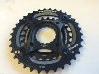
Cutting up a large flange rear freewheel hub and mounting it to the crank fixed sprocket on the right side "might" work, IF I can find a flat Race Face CINCH 28T sprocket that has its' inset lip towards the outer diameter. I think Wolf Tooth might make such a sprocket (?)...

The issues I keep running into are:

1) Left side freewheel crank with RH threads will work fine, BUT most frames (including mine) will not allow a 48T sprocket on the left side.

2) A right side freewheel crank with RH threads that accepts both sprockets on one freewheel like is commonly sold, requires a freewheel at the motor too, BUT no 11mm bore freewheels exist with less than 12T (if you can even find one) and the flip-flop adapters made start at 13T; I need to run a 9T.

3) The FS MTB bike application is a carbon frame and I don't want the weight or complexity of a jackshaft setup. All added weight will be DEAD WEIGHT 90% of the time. Trying to keep that less than or about 6lbs (or about the weight of 2 full water bottles).

4) The motor being used is a simple light weight 9.78:1 geared reduction MY1018 450W 24V brushed motor that needs to be further reduced to a managable cadence speed at the crank: thus the large 5.33:1 (48T/9T) of further reduction goal. The motor specifications state 440rpm at 24V, but I may run it at 36V, so that will increase the rpm's further.

Hopefully that gives you enough information to see what I'm trying to do, so my 230lb 57 year old body can stay in the game for those incredible downhill runs that keep me living extra large. :mrgreen:

Of utmoost importance is that the MTB needs to pedal like there is no additional drag when not under power AND the weight has to be kept to an absolute minimum. Any and all ideas or suggestions are greatly appreciated.
 
You should open your own build thread with pictures of the frame and the motor mount etc.
That unite motor seems not a very good fit on a FS carbon frame IMHO.
All the way you figured out seem to me impractical, complex, improbable or not useful for the objectives.....
 
Yeap. The simple solution is to use this RACE FACE Cinch Direct Mount Double Spider, put a 28T on the 64BCD and 46-48T on the 104BCD and find a 12T 11mm bore 4mm keyway freewheel for the MY1018. That will require me to drag the chain up to the little freewheel. GNG kits seem to be using the 12T X 46T. But I'd prefer to use a 9T X 36T with a single freewheel at the crank for the motor chain sprocket to achieve the same 4x additional reduction and lose the chain drag while riding without power, thus my inquiry here about a strong double flanged freehweel.

Here's the thread I started using the MY1018 as a mid-drive:

https://endless-sphere.com/forums/viewtopic.php?f=28&t=84422
 

Attachments

  • RACE FACE Cinch Direct Mount Double Spider.jpg
    RACE FACE Cinch Direct Mount Double Spider.jpg
    231.9 KB · Views: 1,518
Is there a USA supplier of the Tri-All ISIS 7050 Freewheel Crank arms?

They seem to be well respected as strong and well made. The left and right also look to be symetical, only the right one has the RH freewheel threads machined onto it. I wonder if RH freewheel threads can be machined onto the blank left crank arm too?
 
panurge said:
... That unite motor seems not a very good fit on a FS carbon frame IMHO.

What smaller lighter geared motor would you recommend? The MY1018 450W 24V 25A was the best fit I could come up with. Please give me something better.

panurge said:
All the way you figured out seem to me impractical, complex, improbable or not useful for the objectives.....

Left crank freewheels are out there (least drag). Right side freewheels at the motor are out there (easiest, just bolt-on motor). Right side freewheels at the motor and crank are the standrad setup that most kits use and most custom builders here. Not really sure what you are saying...

I like a Focus Project-Y full suspension MTB, but that just doesn't exist "yet" and the heavy ~50lb+ eMTB's custom or factory built eMTB's pedal like pigs with the power off because of weight and drag. The Focus Project-Y is the direction eMTB's are heading for a good reason! Not looking for a eMTB motorcycle at all.

I'm looking for a light weight way to add electric assist strictly for hill climbing off-road while not changing the pedal drag of a normal MTB when not under power carrying that extra weight; which is how the MTB will be ridden the majority of the time (power off).

Please give me a bettter way or a better motor for this application. Thx.
 
Santa'sLittleHelper said:
I'm looking for a light weight way to add electric assist strictly for hill climbing off-road while not changing the pedal drag of a normal MTB when not under power carrying that extra weight; which is how the MTB will be ridden the majority of the time (power off).

Please give me a bettter way or a better motor for this application. Thx.

Sounds like an application for Velogical's friction roller drive that engages the rim sidewall.
 
Santa'sLittleHelper said:
Wouldn't it be nice if someone made simple light weight dual flanged 64BCD and 104BCD freewheels? They'd even be reversible!

I guy can dream... :roll:
I think that I will get my a$$ in gear and make one. I was hoping that I can buy one but at this point it looks like making one is the only option. The trick is to make it strong and thin at the same time. Interesting challenge. Any suggestions if comes to bearings and type of engagement?
 
Ecyclist said:
Santa'sLittleHelper said:
Wouldn't it be nice if someone made simple light weight dual flanged 64BCD and 104BCD freewheels? They'd even be reversible!

I guy can dream... :roll:
I think that I will get my a$$ in gear and make one. I was hoping that I can buy one but at this point it looks like making one is the only option. The trick is to make it strong and thin at the same time. Interesting challenge. Any suggestions if comes to bearings and type of engagement?

Sorry, but I can't help you there like many others here. I'm a financial engineer not a mechanical one; although I did spend my entire life growing up in the "garage" like so many others in SoCal suburbia and I'm convinced I was a mechanical engineer in a prior life...

If it can be done, make them 64BCD, 104BCD, and 130BCD! :)
 
Back
Top