Converting a hubmotor to a middrivemotor

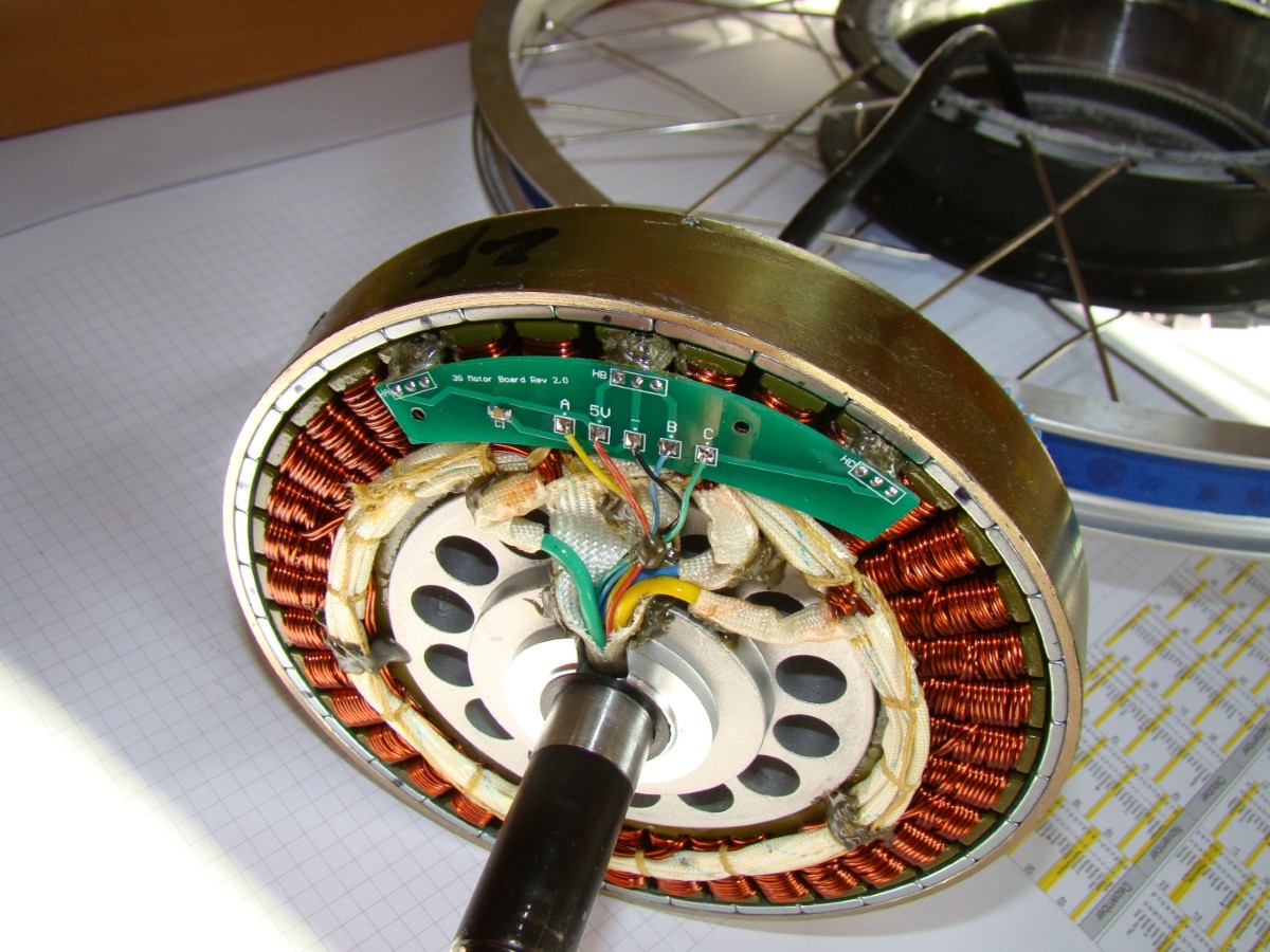
i just read through the hall sensor positioning manual crossbreak posted. really nice stuff.
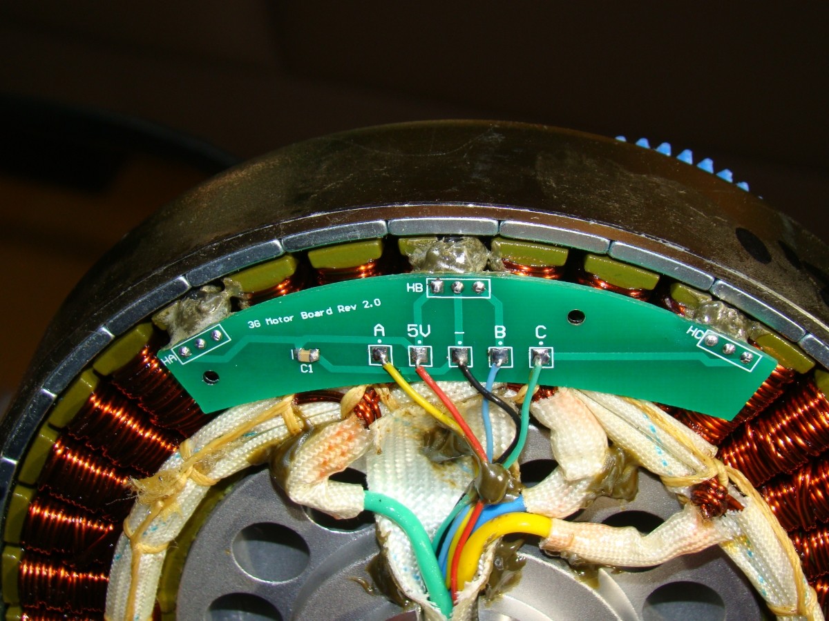
after doing all the math it just showed that the halls need to be positioned 3 slots apart, what they already are. it may be that the distance between them is not 100% exact, but i can't really imagine that.
so i can just do some timing advance to compensate for hall sensor lag and hysteresis. if the kelly controller would be a real FOC controller it would not relate on halls and measure back EMF, which is doesn't seem to do.
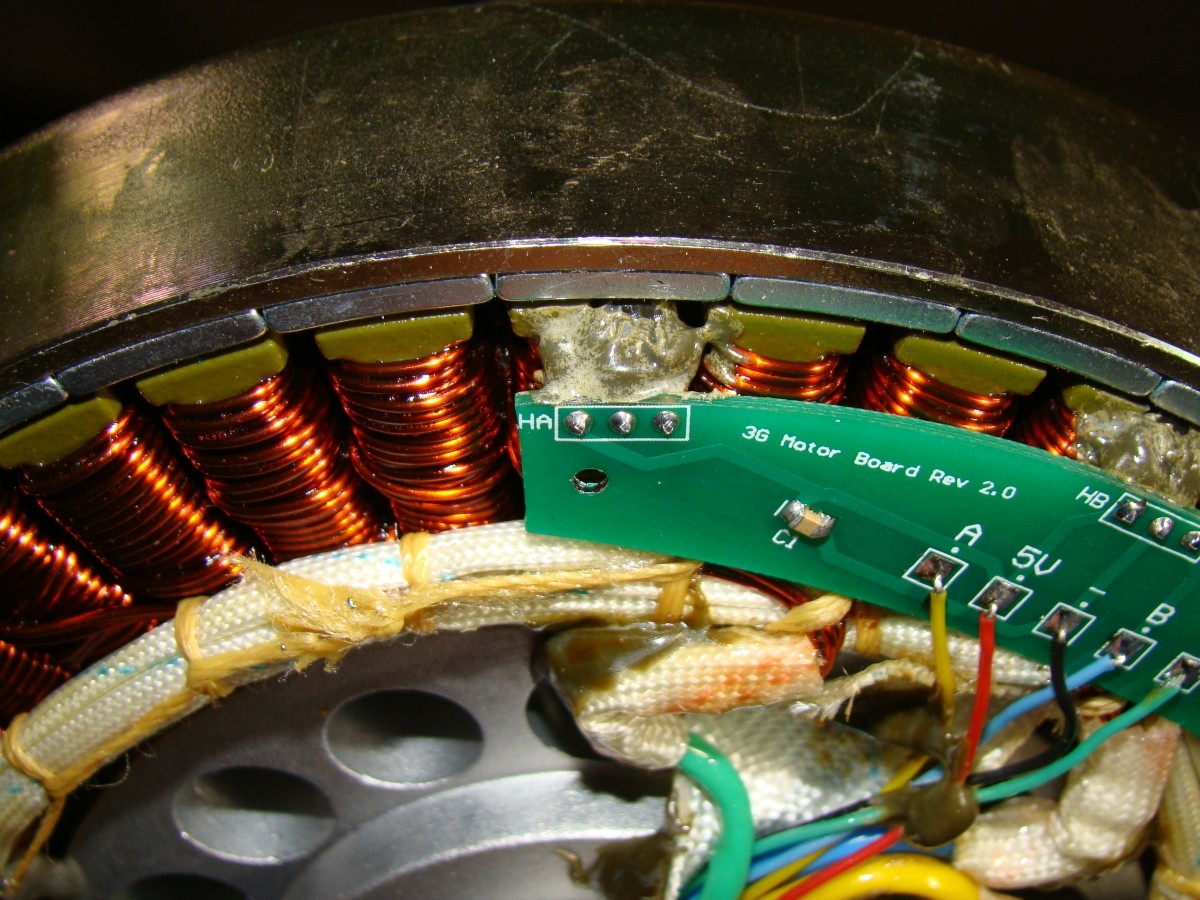
i will make a custom hall board that can be moved around and fixed to the motor and do some more testing.
 
crossbreak, i know you're always interested in no load current of different motors. so i did a measurement with my MAC 6T turning up to 2.800rpm @43,5v sagged. so this is a 64kV motor from my measurement - you claim 69kV in the wiki. so quite similar. this is motor only. no gears, no case. only stator and yoke.
the kelly sine wave is NOT able to do proper hall sensing. so measurement is somehow wrong. you can see that no-load current goes up very linear up to 2.800rpm. this is with the old 0.5mm lams.
the red line is the somehow weird sine wave, and the blue one the trapezoid kelly.

 
thank fechter. exactly what i was looking for. i just didn't search for bmc, and not 5 years back.
this confirms that the mac's timing is somehow weird. finally i got this information confirmed.
so what i did: i milled slots 4x4x2mm into the stator to try different hall positions.
the good news: the controller's self teaching feature works for the very first time now relyiably.
i just can't get halls recognized in the standard position.
but the difference between different positions is minimal. so it seems the controller compensates for that.
still the halls directly in the middle of one tooth seems to be the best by 5-10% depending on rpm.
i will need to do the tests with a kelly trapezoid controller to compare.

Capture.JPG
 
izeman said:
i did cut some new grooves into the "new" 0.3 lam MAC as well.

Keep in mind that doing that shorts the laminations together wherever the metal gets pushed across the lamination edges in each "groove".

So all of those laminations may be shorted together on the hall side of the motor. I don't know exactly how that affects the eddy currents and whatnot, in these cases; I'm sure it's not as bad as having laminations as thick as the shorted area, but I expect it does cause something to happen. I wonder if the effect is measurable in a before-and-after test of some type?
 
This is 100% OT (on topic :)). Doesnt matter if the lams are shorted somewhere. The edd current circles act only locally. I have seen stacks that were welded at multiple edges which did not affect core loss IMO. The old tonxin had this for example. Maybe you still remember, amberwolf? Maybe I can dig out an old pic...not sure if I made a shot of that

How did you make these pockets, iceman? End mill? I'd like to try that.. Looks like a quick and simple solution to a complicated problem!!
 
i thought about shorting the lams as well. the MAY be shorted, but may not as well. i can test it if you like. i still can't say if there is some measureable influence.
making those slots was easy and quick. i mounted the stator in a wise. there where two big round spacers positioned on the stator center that i did clamp to, because you can't clamp the windings ;). then i used a 4mm milling cutter to make 4mm x 4mm wide slots, 1.5mm deep. 5min epoxy to hold the whole hall board in place. was a 10min job.
but the first results where not good. it seems the slots are WAY to far off. i will need to make them closer to it's original position.
reminder to myself: the yoke is turning CCW when looked from above and over the stator.

btw: fechter calculated the halls to move 3.75° (mechanical degrees) back, as the timing of the BMC motor is advanced. so CCW in my case.
stator diameter 135mm, gives a circumfence of 424mm. which is 1,18mm / ° or 4,4mm movement CCW, so more or less one width of a hall sensor. (this is the same calculation the fechter already did in the posted thread. i just repeated it to exclude calculation error, and used my own measurements. getting the same result gives me confidence ;).)
 
hmmm. something doesn't work as expected with the new hall positioning.
good thing first: with the slight offset (4mm), and even with the massive offset (10mm) the kelly sine wave controller finishes auto-config EVERY time without issues. this is working perfectly fine, whereas it is IMPOSSIBLE to do it with the halls at their original position. it just ain't work.
bad thing: it's not running properly. it stutters a lot. it's like a highly oscillating throttle, or accelerating, braking, accelerating ... this behaviour happens with both kelly controllers, but not with the sensorless infineon.
i will have to see if this is an issue with this particular motor (0.3mm lam 8T), as i think i can remember that it did work with the old 0.5mm 6T motor.
more testing to be done ...
 
One method to find the hall locations is to apply constant current to a random pair of phase wires so the rotor lines up with the active stator poles. Once the rotor finds home, one of the hall sensors should be right at the switching point. You could then adjust the hall position so it toggles when the rotor is slightly wiggled. Then pick another pair of phase wires and verify the other halls. This should be the exact spot.

I haven't tried this, but it should be fairly obvious which hall is closest to the toggle point. Setting the halls on this spot will give neutral timing.
In therory, it should be possible to know which hall is supposed to be at the trigger point based on which phase wires are energized.

The constant current needs to be enough to line up the rotor, but not so much that the motor overheats quickly. I'd guess around 5A. For lack of a bench power supply, some big light bulbs in series with a charger or pack might work.

On the Kelly, it sounds like it's trying to do a constant RPM but the feedback loop has too much gain and it's overshooting. If this is happening with no load, it might go away under load. If there are programmable settings, one of them may need tweaking. If you have a choice of speed command vs. torque command, you could try changing that.
 
thanks a lot fechter. that's cool information. i will try do test some more.
weird global warming makes our winter season warmer than we're used to. it's 10C+ at the moment. i guess i will need to finish that motor soon as bike season may start earlier than expected ;)

attached is a screenshot of the PID settings. unfortunately i have no real idea what to change. i changed that from one extreme to the other to see how/what changes, but couldn't see much difference.

Capture.JPG
 
izeman said:
it's like a highly oscillating throttle, or accelerating, braking, accelerating ... this behaviour happens with both kelly controllers
but it did work fine with the KBS-X with original hall position. At least with my MAC it does
 
Yes it did. It seems to be some issue with this special motor. It doesn't matter where i position the halls. The motor behaves exactly the same. And that is with both Kellys. Old and new. Auto config works flawlessly with ALL hall positions but the original one!!!
I did the same procedure with and old 8T MAC and all works fine. Maybe i got some winding issues with the new MAC.
 
@fechter: i did the hall position procedure you proposed. Lab power supply with 3A made the rotor snap to a position where i could be moved by hand.
When i moved the halls by 4mm CCW and observed the hall switching this was 100% spot on. Moving the stator a tiny little bit made then all toggle. So fechter you're 100% correct that moving the halls by 4mm gives neutral timing.
 
izeman said:
@fechter: i did the hall position procedure you proposed. Lab power supply with 3A made the rotor snap to a position where i could be moved by hand.
When i moved the halls by 4mm CCW and observed the hall switching this was 100% spot on. Moving the stator a tiny little bit made then all toggle. So fechter you're 100% correct that moving the halls by 4mm gives neutral timing.

Great work. I never had occasion to try it myself. In theory, this could also be used to map out the proper hall/phase wiring on a typical controller without trial-and-error but I don't know the exact sequence.

Those PID parameters in the Kelly programming will definitely fix the oscillation problem if you can figure out what settings to use. There are some articles on PID tuning on the web, but most of them were over my head.

From https://endless-sphere.com/forums/viewtopic.php?f=31&t=65031&p=1145464#p1145464
Kp and Ki values are used in the PID to control overshoot and oscillations. If they're too high=oscillations, if they're too low=slow response.
 
fechter said:
Those PID parameters in the Kelly programming will definitely fix the oscillation problem if you can figure out what settings to use. There are some articles on PID tuning on the web, but most of them were over my head.
From https://endless-sphere.com/forums/viewtopic.php?f=31&t=65031&p=1145464#p1145464
Kp and Ki values are used in the PID to control overshoot and oscillations. If they're too high=oscillations, if they're too low=slow response.
thanks. in theory i understand how PID controllers should work (from flying quadcopters which need a lot of different PID tuning). but i have NO idea how kelly implemented that feature, and it's missing the setting for derivative factor - but maybe this should be the "speed err limit" and is just not called KD ;). however i hope it can be done.

from the manual:

Code:
Torque Speed KP: Speed Percent Kp in Torque Mode. Range: 0~10000 Factory set is 3000
Torque Speed KI: Speed Integral Ki in Torque Mode. Range: 0~500 Factory set is 80
Speed Err Limit: Speed Error Limit in Torque Mode. Range: 50~4000 Factory set is 1000

These three parameters are used for PID adjustment.
If you think the acceleration performance is very very strong, please adjust them to a lower value respectively.
though the motor/controller combination has this strange effect that letting the throttle go from WOT, running at full rpm, the rpm SHOOTS UP for the blink if an eye, HIGHER then full rpm and then starts to settle down. i can't find an explanation for that effect.
 
izeman said:
though the motor/controller combination has this strange effect that letting the throttle go from WOT, running at full rpm, the rpm SHOOTS UP for the blink if an eye, HIGHER then full rpm and then starts to settle down. i can't find an explanation for that effect.

the adaptto unit does the same if the hall angle and timings are not set properly, and iirc it also behaves like this if i have higher values of field weakening enabled.

btw: this week i have gotten an eZee 350RPM motor (6T i believe) which i bought from ebikes.ca garage sale.
it's stator and rotor design is identical to the MAC's (only not so wide from what i know) but guess what, after taking off the sidecover it looks like the halls are placed differnt^^
tomorrow i will take it completely apart and remove the rotor so that i can see the position better. will definitely shoot some pics and post them here!
 
Wild guess, I'd try lowering the Kp and Ki values and increase the speed err limit. If there's enough range, it should be possible to make the motor respond very slowly to changes in throttle.
 
unfortunately i was not able to take the rotor off because on eZee motors this isn't as easy as it is with the MAC.
but i took some closer pics of the halls. they are shifted about 3-4mm counterclockwise (in the direction it spins). thats a positive timing or pre-ignintion.

V7U41n.jpg


o4xWGP.jpg


VoPTYO.jpg
 
Very interesting posts, guys, reviving this thread.
I also converted a 12t MAC motor for my build, and I'm running it with the Adaptto controller.

Madin, you wrote about the halls: "they are shifted about 3-4mm counterclockwise (in the direction it spins). thats a positive timing or pre-ignintion."
Technically, with the motor viewed from the stator side, it spins counterclockwise, and the halls are shifted clockwise, giving timing advance, is that what you meant? :)

With my Halls right in the slots, the Adaptto didn't have a problem doing the auto-detect.
However, I have a problem with the low-speed control. When I crack the throttle open, the motor immediately starts at what seems like 30% of its max torque. Of course the bike launches abruptly. I can modulate the torque from 30 to 100%, but below that, it's like an On-Off switch. This spoils the fun of an otherwise good combination.

I would be curious to know of other people who run the Adaptto with the MAC mid-drive, successfully or not.
Adaptto basically told me there isn't anything they can do about it. But I find that incredible that this controller can't put out a pulse width narrow enough to accelerate a motor smoothly.

In the pics below, I don't have the pedals installed, and those are footpegs that I made to go trail riding in the snow. I like that configuration much better than with the pedals... 8)

Cheers!
 

Attachments

  • P1060454.JPG
    P1060454.JPG
    211.6 KB · Views: 2,775
  • P1060455.JPG
    P1060455.JPG
    218.8 KB · Views: 2,775
nice built! Looks like you run two chains but no pedals!? why two chains?`one would do the job much better, no :? ??
do you have the old version of the MAC, like in the spinningmagnets tutorial or do you have the new late 2015 one? Would be nice to see some pics of the new MAC internals.

i have low speed issues, too. I run the 6T MAC with FOC kelly KLS and originial hall positions. Motor does not start smoothly from a dead stop. It pulls lots of watts (like 2000) but only stutters and turns VERY slowly. As soon as it turns some rpm it is all fine, all i need to do is let go the throttle of a blink of an eye. Strange.
Autodetection worked fine for me... worked the first time i tried. But there is some sort of rpm limit. it wont turn faster than 2000rpm (32000 erpm), no matter if i use 44V or 54V battery.
 
Finally figured out how to attach images, but not how to paste them in large format. Anyway...

I think that 2000RPM is about the maximum that we can get from this motor. From reading old posts in this forum, the pole count is too high.
 
your pictures are fine. if you click them, they get enlarged.

the controller can do 60000erpm, adappto also. This is 3750rpm. This is definitely a bug. The mentioned 2000rpm are the reasonable rpm for middrive use. the range is 1500-2000rpm. Below it is weak/gets too warm at load. When spinning much faster it gets warm even without any load. Mine eats ~350W no load at 2500rpm.

still...whats the reason you use two chains instead of one?
 
Back
Top