Compact Field Oriented Controller, ASI + Grin, limited run

justin_le said:
mrbill said:
But, I was thinking that iser's problem was related to the resonance Justin and I have observed in drivetrains that are "springy". This would include mid-drives that run motor power through a bike's shift-able rear cluster, or a chain-drive on all but the stiffest of bicycle frames.

Just to be clear, the field oriented controllers work perfectly well with any normal mid-drive bike system like a BBS0X, ecospeed, cyclone kit etc. on a regular diamond frame bike. That's all well within the realm of stiff enough to not see any of this behavior, and it would only be a small fringe if ebike drives that have enough elasticity from the motor to the wheel where you get this instability.
It's easy to understand why a torque control controller has that problem. It would be like towing a trailer that's linked to a truck with a bungee cord, and having as the only feedback for how hard to step on the gas being a force sensor on the trailer hitch, with a goal of keeping that force constant while you drive over different terrain and bumps etc..

I also tested a mid-drive motor of the kind supplied by Ecospeed with the BAC2000 on a bike (Bike 2) whose motor-driven chain drive is roughly 1m from driving spindle to rear cluster (half the length of chain used on Bike 1 that was used for my initial test), but still about 1.5x longer than the BB to rear cluster distance on a typical upright diamond-frame bike. The frame did not visibly flex under high load, but upon shifting the rear cluster, motor power hesitated repeatedly several times before settling down to even delivery. The severity of the resonance was less, but it was still present and too severe for me to want to run it that way long-term.

Recumbent bikes (both long and short wheelbase) with rear-wheel drive, cargo bikes, long-tail bikes, and tandems are likely to have chain-drives longer than those of a regular diamond frame bike. None of these is a good candidate for a torque/current throttle mode controller where motor power is applied through the chain drive.

I hope ASI can be persuaded to add support for a PWM/voltage throttle mode.

mrbill said:
Here is a question I posed earlier that seems to have gotten lost:
mrbill wrote:
5) Can Grin or others give any advice/guidance with the setting of parameters under "Advanced Motor" (field weakening), such as when to use, how much, and the trade-offs?
Thanks.

The field weakening was discussed in quite some depth earlier in this thread, see https://endless-sphere.com/forums/viewtopic.php?p=984725#p984725 and related posts on that page.

Thanks for the link. I must have missed this or forgotten I had read it long ago.

Ideally you would never use field weakening, choose your motor winding and battery voltage so that you are happy with your top-end RPM. But if you are constrained to a setup that isn't as fast as you want it to be and can't afford either a faster motor or a higher voltage battery, then you can use automatic field weakening to get a higher top speed from the motor. The more field weakening current you use, the higher your top speed, and the more your efficiency at those speeds plummets since a large portion of your phase current is simply countering the PM fields rather than producing torque.

I'm not sure that there is much more to say than that. Look at your CA to see how a given amount of field weakening current increases your motor RPM and look at your full throttle no-load current draw to see how much extra power is being wasted to allow these higher speeds, and make the trade-off which suits what you want. The graphs that I included in the post linked above show the general relationship quite well.

In short, there is no free lunch. Fortunately, I selected a system voltage and motor winding that yields sufficient level-ground top speed without field weakening.

It might be convenient if a pre-configured amount and quality of field weakening could be switched on/off while in use. That way it could be employed selectively on a moment's notice, like a "turbo" switch.
 
Hm, i don't really agree with Justins explanation of why a mid drive with some springy-ness in it should oscillate. What it boils down to is that the whole system is not stable, something that should be fixable by setting the correct parameters in the controller...

To get technical, the springyness means there arr extra integrators in the system, so the system is of higher order than just a simple 1st or 2nd order. If your controller responds much faster than the springyness (the added orders from the mechanics) it should be stable.

Like when you're balancing a broomstick. If you are much faster than the acting of the gravity on the stick you can balance it easy. If you are somehow slow then the broomstick will move around wildly as you are trying to ballance...

Anyways, with my FOC controller, also torque throttle (phase current) based, on my middrive recumbent with the motor going through 2 chains: no problems and supersmooth throttle response.
 
Lebowski said:
Hm, i don't really agree with Justins explanation of why a mid drive with some springy-ness in it should oscillate. What it boils down to is that the whole system is not stable, something that should be fixable by setting the correct parameters in the controller...

To get technical, the springyness means there arr extra integrators in the system, so the system is of higher order than just a simple 1st or 2nd order. If your controller responds much faster than the springyness (the added orders from the mechanics) it should be stable.

Like when you're balancing a broomstick. If you are much faster than the acting of the gravity on the stick you can balance it easy. If you are somehow slow then the broomstick will move around wildly as you are trying to ballance...

Anyways, with my FOC controller, also torque throttle (phase current) based, on my middrive recumbent with the motor going through 2 chains: no problems and supersmooth throttle response.

Hi Lebowski:

If you or anyone else has managed to get a mid-drive motor running smoothly on a "springy" drive train with an ASI controller, please post the XML configuration file so I can see your control parameters.

I suspect that not all of the control parameters that affect this behavior are available in the version of BACDoor I've been using (1.5.4). But, I'd be just as happy to learn that I missed a critical parameter when I tried to get stable operation with my mid-drives.

I tried reducing the current regulator feedback constants (Ki and Kp) by a couple orders of magnitude both individually and in combination, but I didn't try increasing them, thinking it would lead to further instability. Torque motoring ramp, both positive and negative, was set to 20ms, as I recall. (It's slightly irritating that BACDoor won't let me view my XML file when I'm not connected to the controller.)

Thanks.
 
I have no clue about the ASI controller, backdoor or XML, i've always built and programmed my own... but the fact that you have something like a throttle ramping is already suspect... i don't have that in my controller, throttle is fed directly into the FOC without ramping...
 
Lebowski said:
I have no clue about the ASI controller, backdoor or XML, i've always built and programmed my own... but the fact that you have something like a throttle ramping is already suspect... i don't have that in my controller, throttle is fed directly into the FOC without ramping...

Hi Lebowski:

Even though you have no advice specific to the ASI controller family, you've given me something to investigate. I will try increasing the current gain parameters and reduce the throttle motoring ramp rate to 0 or 1 ms (which is essentially zero--even 20ms suggests a reaction time shorter than the period of the oscillations I'm getting) to see if that helps.

Thanks.
 
Even though you have no advice specific to the ASI controller family, you've given me something to investigate. I will try increasing the current gain parameters and reduce the throttle motoring ramp rate to 0 or 1 ms (which is essentially zero--even 20ms suggests a reaction time shorter than the period of the oscillations I'm getting) to see if that helps.

Too tight for controller if set very small fraction of the time, this is liable to over current.
 
Any latency in the controller will make loop tuning very difficult.
It seems like there should be a way to make the software figure out the tuning by itself using some kind of fuzzy logic that constantly adapts.
Maybe next year.
 
justin_le said:
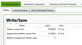
Set this to say 125% of instead of 63% and then you'll have up to 1500 watts into the battery during regen. Set this to 200% and you'll have up to 50 amps of regen current into the battery. This kind of stuff where we're trying to make our own phaserunner configuration software more intuitive to see and change than ASI's Bacdoor package.

I set this to about 132%, which should be about 33 Amps to the battery. Then I went out and did a test ride.

https://ridewithgps.com/trips/7732920

When I was coasting down a long hill at speeds up to 65 kph my peak regen current at maximum commanded regen was 27.5 Amps. It was an improvement over the 15 Amps maximum I was seeing earlier. Is there another constraint I should relax to enable the full 33 Amps of regen, or do I just need to find a steeper hill that gets me to a higher speed? Btw, speeds greater than 55 kph I'm getting "natural" regen just by coasting, so at 65 kph I am seeing -20 to -25 Amps without commanding any regen.

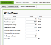
[...] at low speeds, your regen is no longer being battery current limited because of the very low duty cycle in which the regen current flows back into the pack, so the regen phase current is able to reach the full 74A that you programmed as your max. If you weren't battery current limited, you'd have this same braking force at all speeds.

Would this explain why at low speed I am able to get full regen braking force but observe fewer amps flowing back into the battery?

For example, while descending a steep hill, speed around 25 kph, I regularly saw -20 to -25 Amps. Even better, I did not observe the motor heating to the degree I saw with the Infineon regen braking. Very nice.

But, on my particular test route, the bottom of the descent (at about Mile 43) requires slower speed to negotiate some sharp, off-camber corners, so I decelerated using regen to the 15-20 kph range. As my speed dropped I got the same regen braking force for a given regen setting, but less current flowing into the battery. Worse, I noticed the temperature of the motor climb quickly even as the regen current dropped!

As I slowed further, below 15 kph, battery current turned positive, as much as 20 Amps at the moment before I came to a complete stop. (I set the CA3 to 0.02 Seconds display averaging to see this.) During most of this descent at >20kph I could see motor temperature climb gradually from 60C to about 80C, warm but not alarming. As the controller sent less current to the battery and even began to draw current, the motor temperature climbed over an interval of about a minute to 97C.

Is there some additional setting required so that regen current is sent to the battery at all speeds and is not shunted or dissipated elsewhere such as the motor coils? Or, for most efficient operation would I do best to set a minimum regen brake speed and use my friction brakes in the low speed range (e.g. <10kph) where regen is apparently inefficient?

In spite of my complaint, the regen % on that test ride was 18.5%, higher than I've ever seen it. Using the Infineon controller's regen I might see 10% at best, usually around 8%, on this route.
 

Attachments

  • batterySetup.PNG
    batterySetup.PNG
    8.1 KB · Views: 3,564
  • motorNameplate.PNG
    motorNameplate.PNG
    10 KB · Views: 3,564
mrbill said:
Lebowski said:
I have no clue about the ASI controller, backdoor or XML, i've always built and programmed my own... but the fact that you have something like a throttle ramping is already suspect... i don't have that in my controller, throttle is fed directly into the FOC without ramping...

Hi Lebowski:

Even though you have no advice specific to the ASI controller family, you've given me something to investigate. I will try increasing the current gain parameters and reduce the throttle motoring ramp rate to 0 or 1 ms (which is essentially zero--even 20ms suggests a reaction time shorter than the period of the oscillations I'm getting) to see if that helps.

Thanks.

My throttle motoring torque ramps were set to 50ms. I changed them to 1ms for this test.

Then for the current regulator feedback gain parameters, I tried higher settings, as much as 100x, Ki (integral) and Kp (proportional) gain parameters, but saw no reduction in oscillation upon changing the drivetrain load due to shifting gears, something I can easily do in the shop while placing a friction brake load on the rear wheel. Setting Kp more than 10x higher than the default caused a controller fault, and even short of that generated unhappy squealing noises from the motor.

Settings 1/10 the default did reduce (but not eliminate) the oscillations, but they damped behavior so much that I had to wait 10 seconds for the motor to ramp down power to zero after commanding zero throttle, rendering that setting unusable in practice.

I await a PWM/voltage throttle mode for use on my mid-drives.
 
When I was coasting down a long hill at speeds up to 65 kph my peak regen current at maximum commanded regen was 27.5 Amps. It was in improvement over the 15 Amps maximum I was seeing earlier. Is there another constraint I should relax to enable the full 33 Amps of regen, or do I just need to find a steeper hill that gets me to a higher speed? Btw, speeds greater than 55 kph 1.jpgI'm getting "natural" regen just by coasting, so at 65 kph I am seeing -20 to -25 Amps without commanding any regen.
Try 120%~130% for attached parameters.
 
iser said:
Try 120%~130% for attached parameters.

Hi iser:

For both "SOC" and "voltage" parameters?

I need to take care not to let regen to push my battery voltage above 58.8 (4.2v/cell), about 122% of the 48-volt rating. I'd prefer to see some scale-back before that to account for any cell imbalance. But, I might try something like 118-121% as the scale-back range. It's quite possible my battery voltage was being pushed into the scale-back range yesterday. I started at 4.1v/cell and did not discharge the battery below 50% SOC. I confess I did not observe battery voltage while under heavy regen as I was busy watching current, power, and the road!

The controller knows nothing about my battery SOC, but your pointing out this parameter reminds me that due to the settings of other parameters elsewhere in BACDoor, the SOC rollback settings may be constraining regen current. I will try increasing these so that they are never binding.

I see why Justin wanted to write his own Phaserunner configuration software.

Thanks for the suggestions.
 
Hi iser:
For both "SOC" and "voltage" parameters?
Yes, all these are key parameters for regen current. If your battery is near full charge and trigger the threshold of starting voltage or starting capacity, the regen current will decrease.

Do u have the datasheet or spec of your hubmotor?
 
Lebowski said:
Hm, i don't really agree with Justins explanation of why a mid drive with some springy-ness in it should oscillate. What it boils down to is that the whole system is not stable, something that should be fixable by setting the correct parameters in the controller...

Hi Lebowski, to clarify I wasn't saying that it "should" oscillate, but more explaining why it's understandable that you would run into instability problems in this kind of system with a controller that's actively doing torque feedback compared to one that is just open loop driving the motor at a given voltage. You definitely have a lot more expertise and experience in the nitty gritty of control loop tuning than me and like Bill I'm also quite interested in our input here.

A bicycle chain linking motor to load is not what I would call sufficiently "springy", but I'm curious if you have any test bench setup here you could put a much more elastic coupling between your drive motor and the load device, say where between zero to full torque the motor can rotate several electrical RPM's when the load is still fixed?
 
Hey guys, we've been getting a lot of inquiries about the availability of the next run of Phaserunner controllers since I had set a Jan 31st ETA date on our website, but it's been a real challenge to try and setup this new production run while simultaneously trying to juggle everything involved with moving our entire shop and business to a new location at the end of this month. I'll be posting some sample pictures of the updated design and features soon, though I don't expect we'll have more than a handful of built up units to offer till March.

In the meantime though we have been making good progress on refining the simplified user setup software. As Bill said even after quite successfully working his way around Bacdoor:
I see why Justin wanted to write his own Phaserunner configuration software.
We've just finished the V0.6 release for windows and linux:
http://www.ebikes.ca/downloads/Phaserunner_Software_v0.6.exe
http://www.ebikes.ca/downloads/Phaserunner_Software_v0.6.tar.gz

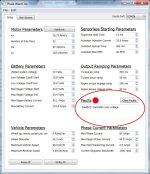
There's a little glitch in the windows version with the COM port drop-down window location being misplaced until you first resize the main window, then it's where it should be. At the surface the main difference that you'll notice is that it now shows your controller fault flags and replicates the "clear faults" button.
Faults Flags.jpg

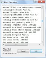
There's been many updates in how individual parameters are named and sensible min/max bounds imposed on them, so you can't say set your start regen voltage higher than your end regen voltage etc. And if you used the "custom parameters" list, you'll notice that the bitfield vectors for all the boolean settings are now broken out into individual checkboxes, the parameter address value is shown, and we try to clearly indicate which parameters are scaled/interpreted differently than in ASI's documentation.
Bitfield Parameters.jpg

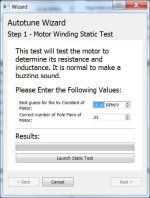
There are also several changes to the motor autotune wizard. The static test for instance now runs the static discovery 3 times to make sure that the measured Ls and Rs values are consistent, and if you have 1 of the 3 phase wires disconnected during this process then it will alert you to this rather than just saving an erroneous winding parameter.
Autotune.jpg

If there are people who have gone through the process of configuring a Phasernuner to work with their motor using Bacdoor as we'd previously outlined here, we'd be really keen to hear your feedback on how this compares, and if it strikes the right balance of letting you edit and customize the stuff you care to tune the controller for your system about while hiding most of the rest. The next phase of the software development is to have a separate "dashboard" tab which shows in realtime all of the live voltages, currents, signals, motor RPM's and other details of the running motor. So the "Setup" tab will be where you configure all the options, and the "dashboard" tab will show you everything going on when you hit the throttle.
 
cavallo pazzo said:
After many trials, it appears the smoother ride allows me to clearly lower current in all 3 modes for the same net result, leading to a huge gain in consumption. On one of my daily drives, 14 km with approx. 450 m of negative and 450 m of positive elevation, I was able to move from 8 to 5.5 Wh/km in slow mode, and from 11.5 to 8.5 Wh/km in fast mode, for same travel time and effort.
Motor is running at lower temp, casing is around 42°C instead of 50°C with Infineon controller, and everything is much smoother.

I am able to confirm a significant reduction of total energy consumption and a reduction of maximum motor temperature when driving a Nine Continents DD hub motor (M3006RC) with an ASI BAC2000 controller compared to an Infineon controller. I wrote up my results here:

http://mrbill.homeip.net/hybridBike.php#inf2asiControllerComparison
 
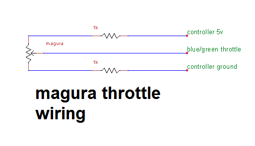
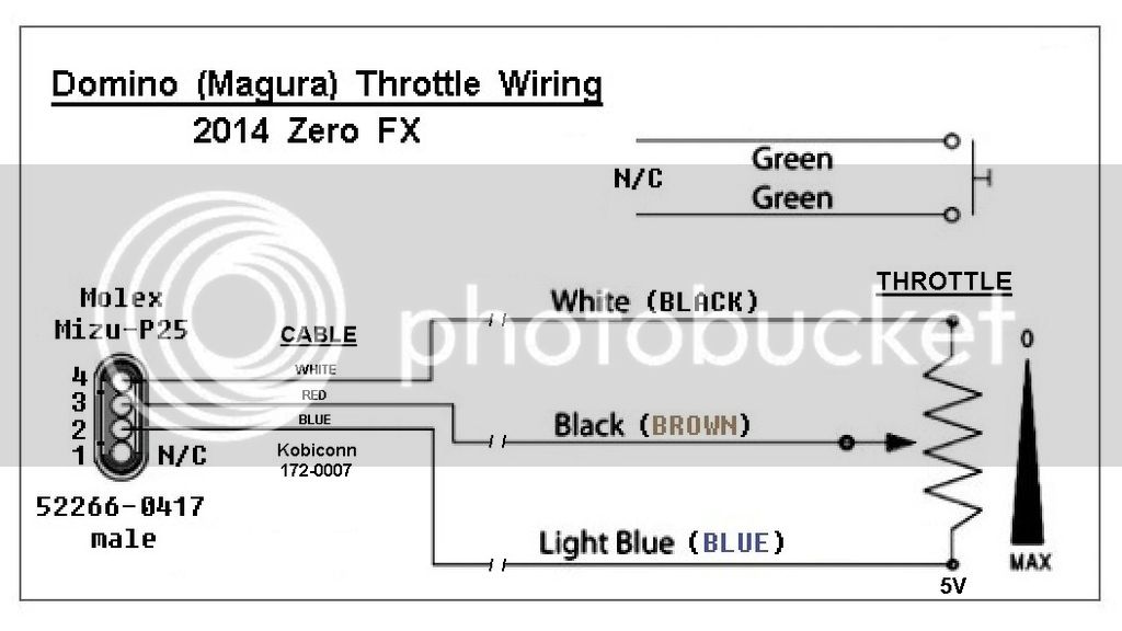
I'm having trouble setting up a Magura potentiometer throttle to work directly with one of the prototype batch Grin/ASI 500s.

With the throttle in closed position, I get:
5 kohms between the blue and brown wires.
5 kohms between the blue and black wires.
4 ohms between the brown and black wires.

So, the brown wire of the throttle seems to be the wiper.

Using the Grin wiring harness to ASI specifications(table 1), I've connected the blue and brown wires to every plausible combination of sockets, with no success...

Could someone please tell me which are the connections I should be using? That would be a good place to start..... :) Thanks!
 
VtKIn.png


Throttle%20Replacement%20Schematic%202%20Domino%20-%20Magura.jpg
 
Back
Top