18650 spot welding -how to- ULTIMATE REPOSITORY

Interesting, I should have tried this. Does the whole strip need to be cut?

Seems like only the part you weld needs to be cut. Reason I ask is I intend to solder a wire to the strip before welding and will not be able to cut the entire strip.

I got to make fast decisions here because My new frame is here next week and want to get my Q76R rolling as soon as possible.

I am considering cutting .2 nickel into 27x12 mm strips and using that between each two cells.

I got lots of .3 x 8 nickel also, may try to see if that welds good with the cutting, because it was not weldable without cutting it.

I wish I didn't blow my fets on my welder by trying to use too much power.. oh well got to wait for parts now.
 
OR- I think there's info here already on the slots. Makes a big difference in ease of welding. Forces current down into the can. Must have one electrode either side of slot for it to work ( definitely not on same side).3 mm is very thick- not really that good for the can cause its too strong but you might be ok.
If you were almost able to weld .3 without slotting then I'd say you'd be able to with slots.
 
Skrzypas said:
Lurkin said:
You can also buy pre made strip this way.
Where?
You can find nickel strips like this on Aliexpress:
http://www.aliexpress.com/store/pro...-for-Electric-vehicle/126412_32597197526.html
Before order try to check if this are real nickel or just nickel coated stripes, because there is a big difference. I think we shoud have a "recomended nickel stripe sellers" theme here on the forum, because a lot of newbies (me included) doesn't want to make the same mistake like some other ES members to buy a kilo of pure nickel stripe and then use it as a door stopper. :D Actually there shuld be a list for every part of recommended parts for e-bike builders.

You will also need some spacers for your cells to form a nice looking pack:
http://g01.a.alicdn.com/kf/HTB1R6Cf...650-Spacer-Radiating-Holder-Bracket-Black.jpg
 
Great thread
 
Coming back to the "grooves" or "linear holes" in the stripes: has anyone an idea how to do / buy a DIY puncher to make such ca. 8 mm long holes?

I'm thinking of converting an office puncher now.
 
Skrzypas said:
Coming back to the "grooves" or "linear holes" in the stripes: has anyone an idea how to do / buy a DIY puncher to make such ca. 8 mm long holes?

I'm thinking of converting an office puncher now.

I believe someone mentioned to use a dremmel. Just get the right thickness blade and grind the groove?
 
Scissors for end cuts, dremmel for middle ones. Aim for about 2-3 mm beyond the closest weld as a starting point for length. Prob 8-9mm as a start, as narrow as possible. Longer cuts have a bigger effect (to a point) but reduce strength and current carrying. I have found a mild benefit with even just a scissor slice- ie no material removed and sides of cut still touching. Keeps as much nickel as possible remaining... increased resistance across slice must be just enough.
I just had a thought... A punch of the right shape would be awesome cause it can be tedious work doing all those slices. :?
 
I did some testing with .3 nickel and cutting it down center. Makes a big difference when it is cut in half.

However, I am not so sure if I want to deal with .3 nickel. This is what I found by cutting .3 nickel in half.

It is hard to get consistently good welds compared to using .2 and .15.

many times I can break the .3 nickel off without pliers. Even when I get a good weld the .3 nickel seems easier to break off than .2 nickel. I believe the extra pulse time or amps needed to weld .3 nickel makes the weld less strong and more burnt.

With .3 nickel I found that I usually have one side that welds better than the other. This isn't the case nearly as much with .2 and .15 nickel.

That being all said, it is a must to cut or make grooves in the .3 nickel. It is weldable, but I've had too many issues with it and decided not to use it. I just don't feel confidant using it because of too many inconsistencies.

For my build I will cut custom .2 x 12mm nickel strips from a larger nickel sheet and this gives me exactly the same current handling as .3 x 8mm nickel that I have. The .2 will have much more consistent welds and is also much easier to weld.

Here is a decent weld below on .3, pulled off with holes in nickel.
 
Offroader said:
For my build I will cut custom .2 x 12mm nickel strips from a larger nickel sheet and this gives me exactly the same current handling as .3 x 8mm nickel that I have. The .2 will have much more consistent welds and is also much easier to weld.

Where did you buy a 0.2 nickel sheet?
 
Skrzypas said:
Offroader said:
For my build I will cut custom .2 x 12mm nickel strips from a larger nickel sheet and this gives me exactly the same current handling as .3 x 8mm nickel that I have. The .2 will have much more consistent welds and is also much easier to weld.

Where did you buy a 0.2 nickel sheet?

I bought this, but it is on the expensive side. You'll have to do the math to compare it to other nickel sold. It could be up to 50% to 100% more expensive.

I tested it with salt test and grinding test, and it is 99% nickel. Right now this is the only confirmed .2 99% nickel that I know of.

What we need to do is contact one of these sellers to make a custom size for us. I think .2 x 12 mm would be best. I guess we could also use .2 x 18mm to maximize width.

http://www.ebay.com/itm/99-96-Pure-Nickel-Ni-Metal-Foil-Thin-Sheet-0-2mm-x-90mm-x-1000mm-EYL-3-/181472007058?hash=item2a40931392:g:MAcAAOxyeZNTSPEu

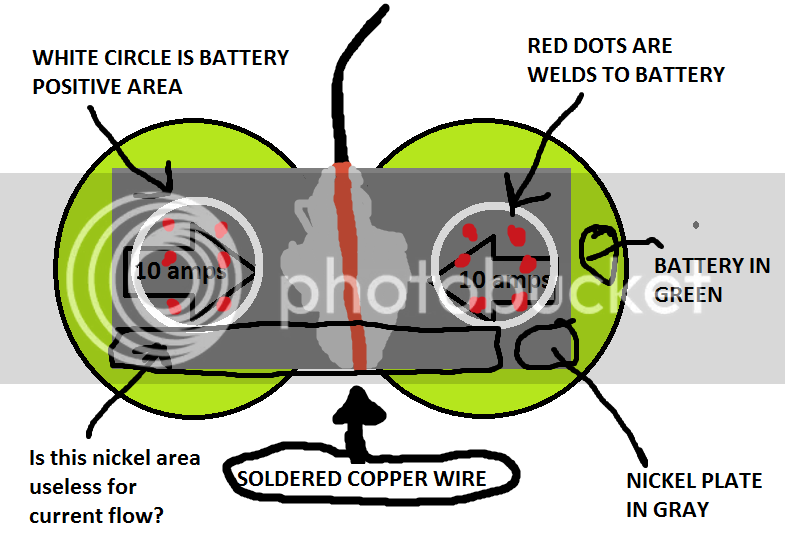
I'm going to cut my nickel in 12mm x 27mm strips to fit between two cells to save on cost as each of these will have a 16 AWG wire soldered in the middle to connect the cells in series. I'll then solder a thin strip for balancing over this. No reason to use the .2 nickel to connect cells that only need to be balanced.

Here is what I plan to do, I made this picture for something else but here it is.

 
Skrzypas said:
From what I observed during my initial tests, it is very important how you weld the second stripe. The current does not like to flow through a small spot weld and chooses to flow mainly through the first layer of the metal stripe.
I was testing that with steel stripes I couldn't reach 50% "efficiency of adding more layers". I can make some specific tests if you want.

To avoid this it is better to spot weld two stripes at once to the cell terminal. From what you said before it is rather clear you won't be able to do it in this way, but please - try and share the results.

I don't get why you recommend welding two layers at once.

I test welded here on top of each other. First .2 nickel, then .15, .15 and .15. For 4 layers.

Each layer welded very easily to each other and the welds were very strong, I wasn't able to pull them apart by hand and when I finally did they ripped holes in each other.

If you need to pass current just get .15 nickel and weld layers, very easy.

 
What I observed is when you weld multiple layers at once, the current path is:
1. from cell terminal to the weld
2. from the (thick) weld, the current distributes between 2-3 stripes pretty evenly.

When you weld stripes your way, the path is:
1. from cell terminal to the weld
2. from the weld to the first stripe
3. and then the current can choose either run where it should through the first stripe or "choose a narrow path" through another weld to the second stripe.

Option 2 has potentially higher resistance and more heat generation.
 
Hey everyone, need some advice here.

When using the hot glue, why did the person in the video shoot the glue from the top after already gluing the cells earlier?

Please watch the first 30 seconds of the video, but look at 0:27 where he squirts the hot glue down already glued cells.

What I don't understand is why do this after he already glued them at 0:22 ?

I'm surprised he was able to squirt anything down after the glue already dried.

Thanks.

[youtube]5L9hOVG_0RQ[/youtube]
 
Offroader said:
Hey everyone, need some advice here.

When using the hot glue, why did the person in the video shoot the glue from the top after already gluing the cells earlier?

Please watch the first 30 seconds of the video, but look at 0:27 where he squirts the hot glue down already glued cells.

What I don't understand is why do this after he already glued them at 0:22 ?
Why not?
Makes the pack as compact as possible.
 
What I question is it looked like he ran the hot glue down the sides of the cell, then later sprayed it from the top of the cell. So he would be spraying hot glue down already glued cells.

Maybe I misunderstood and he only sprayed it down the top on some of the cells, and ran it down the side for some of them.
 
OP here also the builder :eek:

In that case specially the battery was made first sticking and welding 15p blocks, and then sticking each other up to the final shape. As you don't have time to put 8 strips of silicone and then stick the modules (silicone would harden), you are obliged exclusively in that case to insert the glue over the anodes and cathodes holes to mount 15p blocks each other, and only a pair of large strips along cells belong to battery width.

However, in standard cases and battery constructions, despite you use a generous quantity mounting them one by one, (adding the silicone over all the height in the space between 3 faced cells), once you have the block, or the whole battery, is greatly recommended to add a final portion between anodes and cathodes in the small hole each 3 faces cells let, with this method you increase enormously the strength, compact and integrity of the final battery, making much more durable and resistant over the years of vibrations and extreme seasons temperatures.

Secondary you are making the anodes and cathodes sides of the battery full of small toeholds along the whole surface, increasing slightly the anodes protection, specially when the battery is installed in plain face cases
 
I also wonder if a good amount of hot glue surrounding the cells adds some thermal advantage or disadvantage.

On the one hand, it would act as a thermal delay mechanism, kind of like how wax is sometimes used. It would also prevent the heat of one cell transferring as quickly to surrounding cells.

On the other hand, it probably adds unwanted insulation to the cells, and once it gets hot/melts the heat will remain for some time in the whole pack.

I was thinking of padding my future built packs with 1mm or 2mm thick thermal padding (used for GPU's) underneath the heat-shrink. This way if the pack is inside a metal container like a frame, the heat has a pathway (although not optimal) to reject some excess heat. The only catch to this is in the winter you kind of want some insulation to warm your pack. I guess there are drawbacks either way unless you employ some active thermal management system.

Cheers
 
> I also wonder if a good amount of hot glue surrounding the cells adds some thermal advantage or disadvantage.
> On the other hand, it probably adds unwanted insulation to the cells,

It really depends on if your finalized battery block will be allowing air to flow through it like this rare pack:
https://www.facebook.com/media/set/?set=a.964566760247297.1073741836.858577547512886&type=3
12795390_965083720195601_7422283553487513616_n.jpg


This is not very typical though - usually the battery packs are covered in one big shrink-wrap, almost air-tight.
I read in one of the Pack-Building guides that people make the mistake of assuming that it is good to have some Air-Gaps between the cells for cooling.
So they use Spacers between cells instead of packing them tight in a honeycomb pattern.

But air is a very good insulator when it cannot move:
Just look at this list: https://en.wikipedia.org/wiki/List_of_thermal_conductivities
Air has 0.024
Hot Glue: I would estimate from similar substances ~0.25
So Hot-Glue passes on heat roughly 10 times better than air!
-> The easiest way for a battery in the middle of the pack to lose heat is to pass on the heat to glue and other cells towards the outermost cells.
Any non-moving air-layer in between is not helping...
Ulli
 
I think all battery that has space/spacers between cells has it for not touching from each other. And every big manufacturer dose that, it has some type of spacer, it is safer. If the glue snaps (small probability although) you will get cells rubbing from each other and finally short out.
 
Hey guys, I've got a problem. I just hooked up my BMS. When I reached a full charge some lights came on where the balancing cables went in. It was a little warm while these lights were on. It was strange. I don't know, maybe that was normal. But overnight it lost charge from 67.2 volts down to 66.6 volts. That's definitely not normal. What is going on? Do I need to disconnect this BMS and get a new one? I scared that it's going to ruin my brand new Samsung 25r cells. What do you think?

Here is the link to the BMS I used: http://www.aliexpress.com/item/16S-Li-ion-Lipo-Batteries-Protection-Board-BMS-System-60V-67-2V-50A-Continuous-Discharge-Current/32263328170.html

thanks all
 
Back
Top