
Skrzypas
10 W
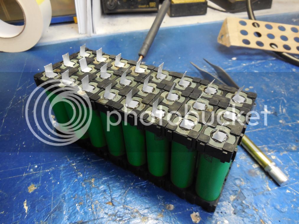
Do you think it's a good idea to solder the thick wire a few nickel stripes and then spot weld the nickel to other nickel stripes being spot welded to the cells before?
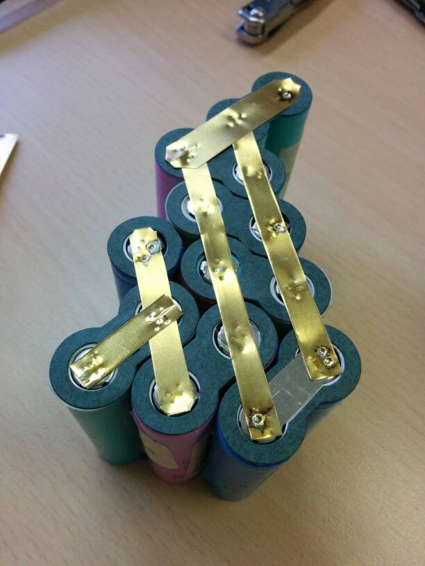
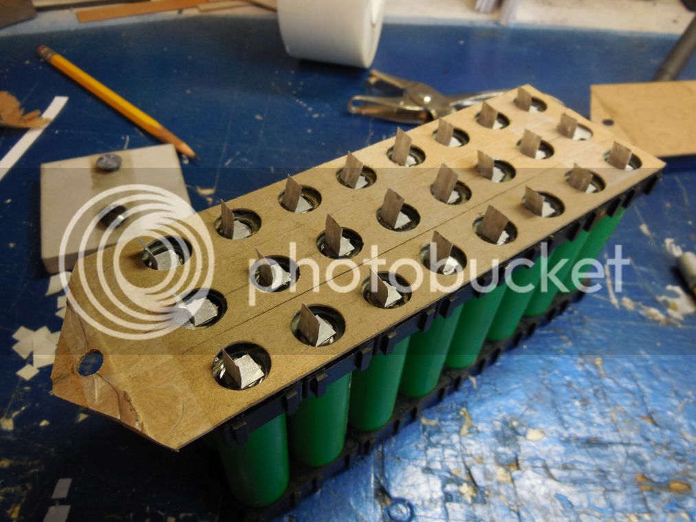
If this is a battery for normal bike frame I hope you will make good and tight box for it. And don't forget the lenght of your pedals... You want to pedal too, I guess.DVDRW said:My first 18650 pack plan. 22s18p
Wish me luck!
Skrzypas said:https://www.fasttech.com/products/1425/10012815/3952701
Ordered 300pcs.
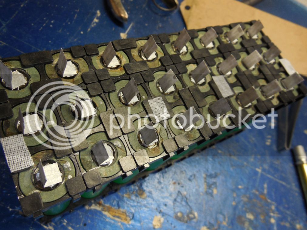
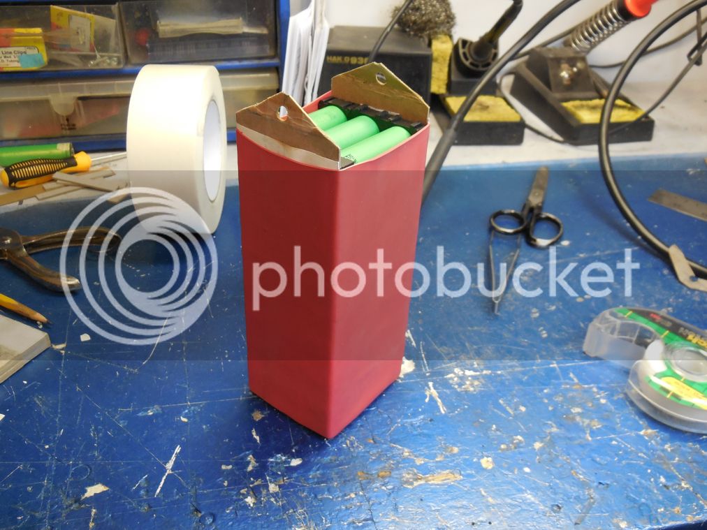
Until they arrive I'll continue welding negatives
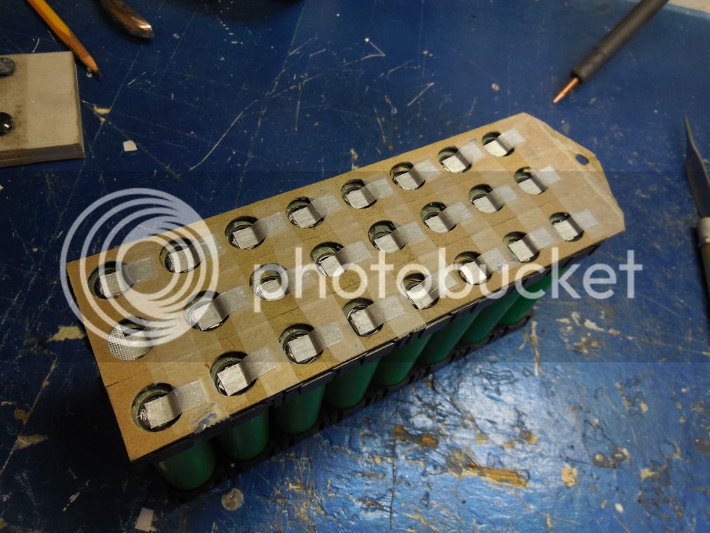
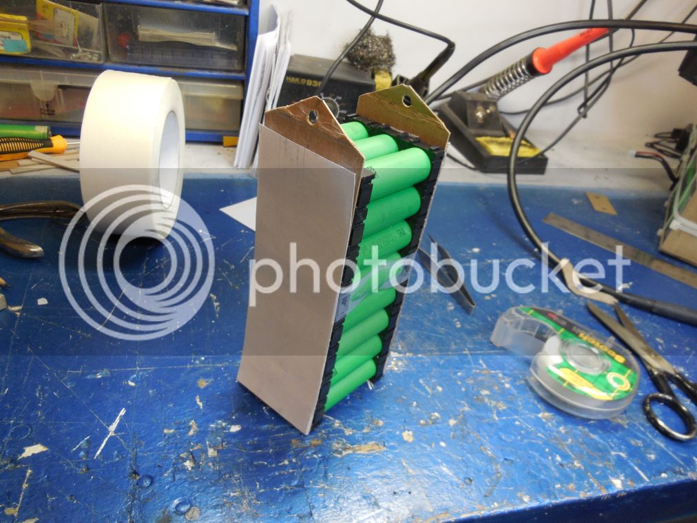
 This would not be for a bicycle but for something bigger. Motorcycle, car, power station. The principle is the same for any parallel combination. Some will find this similar to the Tesla Model S modules, that's because it is.
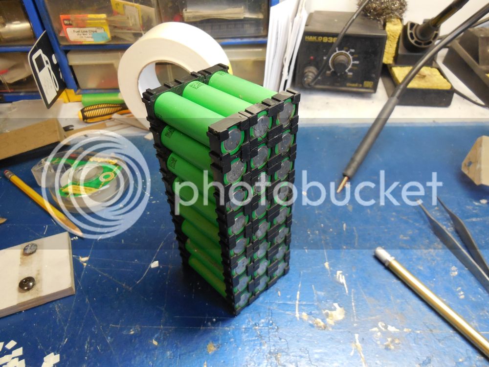

ian84 said:Thanks guys for the replies.
yes indeed copper connection will be ultimate.
DrkAngle threads? where is he @ on the forum? can someone link me to it thx.
Back to my Questions can someone kindly address each point?
I don't have to pull 50A, i want to see what is the limits.... an approx figure...
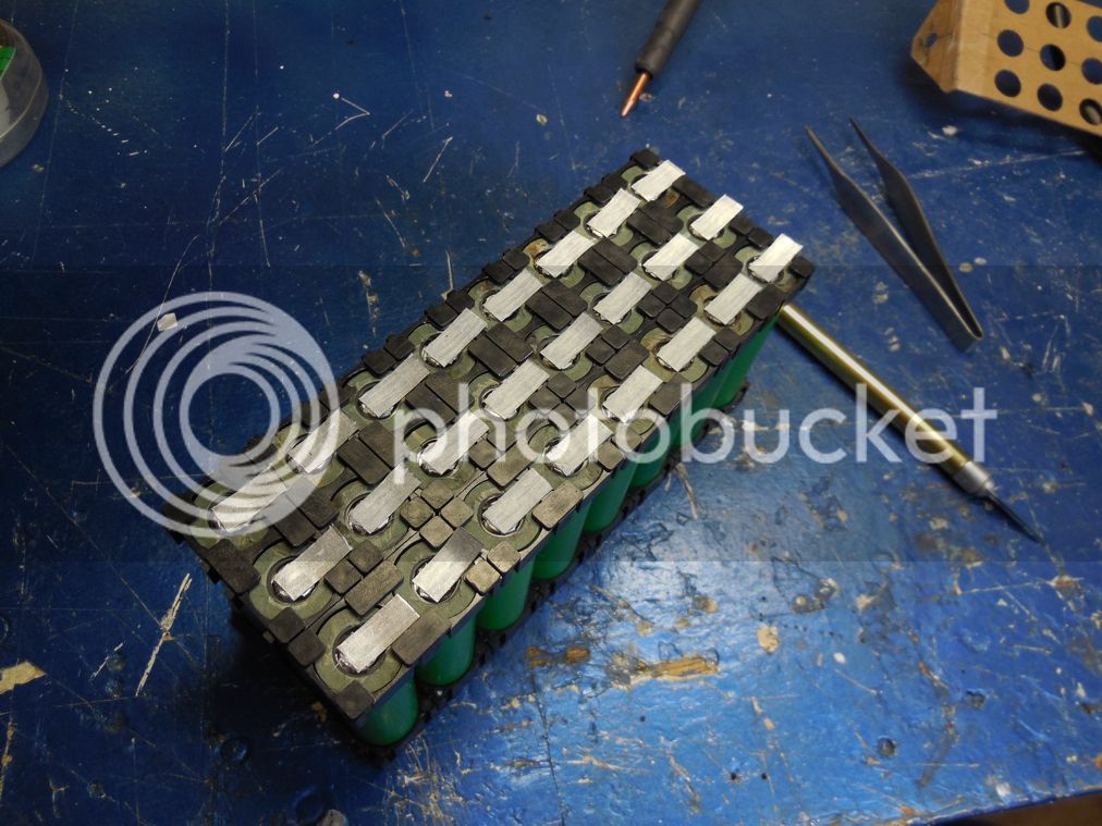
I notice u only put copper wire over the series connection and not soldering copper wires to the parallel to beef it up...
why is that ? In the P group current is divided out on all cells in the group... and the whole current load is then transferred across the Series copper wire... is the total current also divided out on all the copper wired in the Series connection ?
Just realised your pack is probly unfinished. . As your P are not connected yet. . Only 1+1 what did you end up with? Using copper wire to connect all the (1+1)?
