JP spot-welder, FET-switched, timed adj. pulse

fechter, you were helping me before with designing my pack with wires.

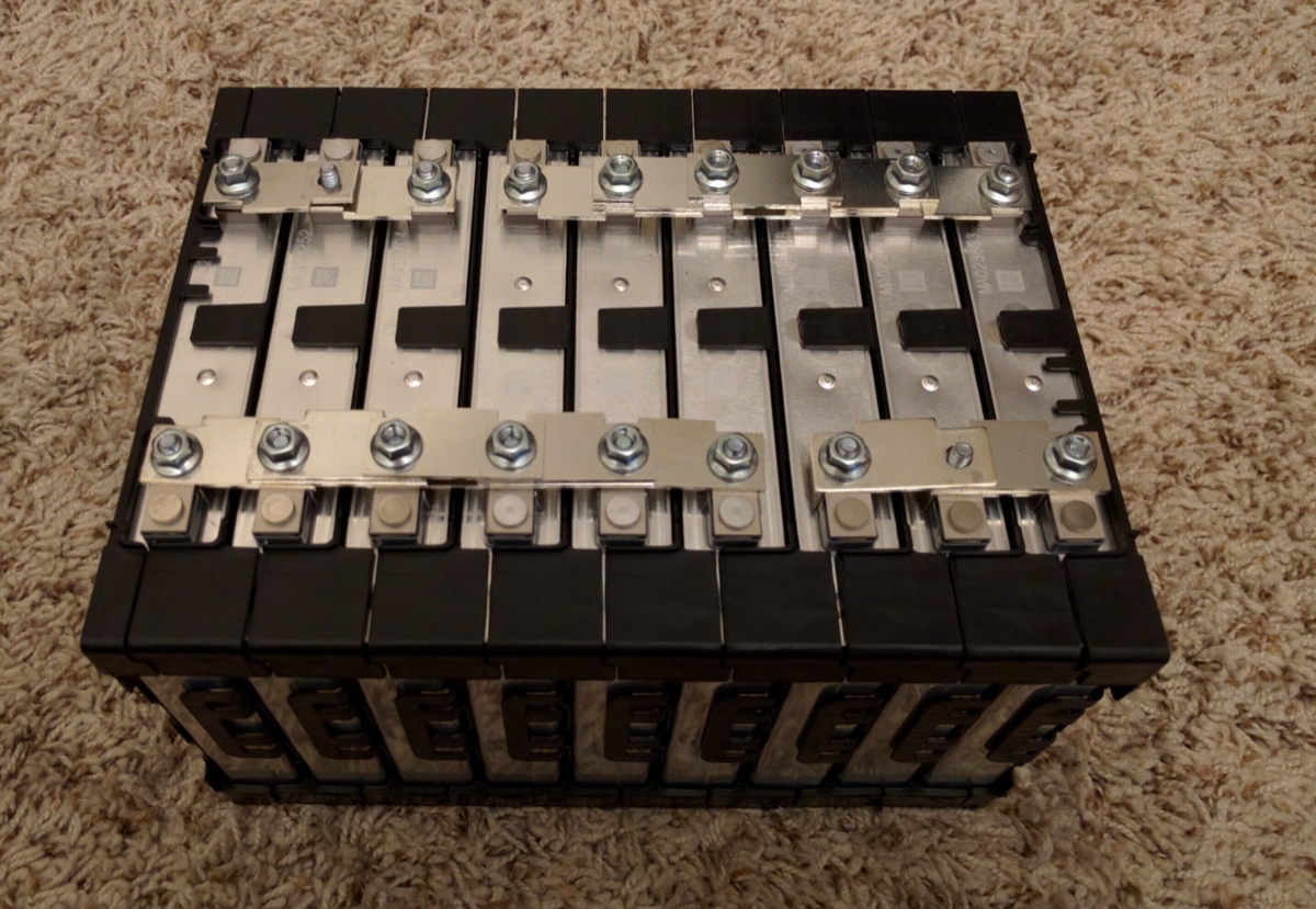
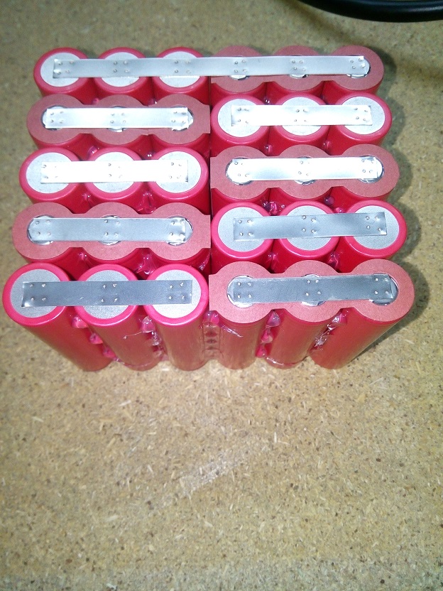
Each wires connects two cells to another two cells in series.

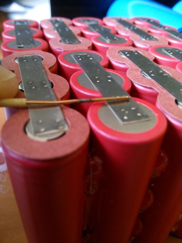
I connected half of the pack with wires as shown in the picture. All wires are equal length between series groups. I'll add a small balancing strip to all cells.

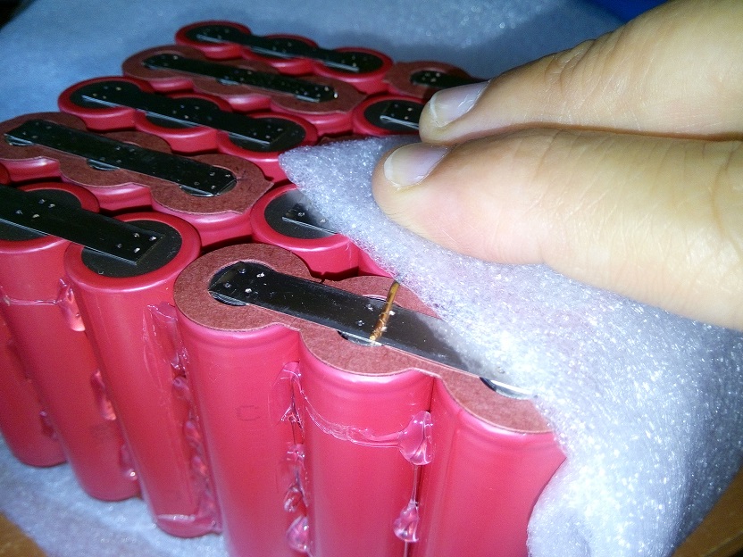
I have not done the other side.

My question is, do the same two exact cells need to be connected with the series wires to the other cells on the other side?

Or as long as I connect all 14 cells with the series wires, it doesn't matter which cells they connect to on the other side of the pack?

I don't think it would matter, but it is hard to figure out. And I may be overlooking something. I believe as long as I am pulling current from all wires it wouldn't matter.

I hope you understand what I am talking about here. The reason I don't want to use the same cells on the other side is because it makes it more difficult then if I just choose randomly.

Thanks. If anyone else understands then you can also comment.

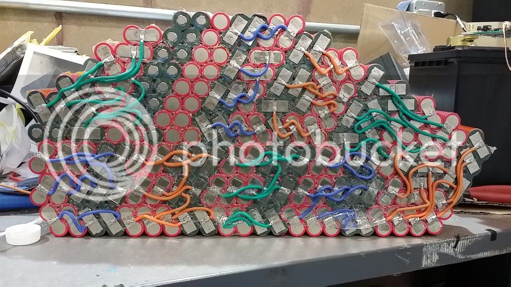
On the bottom image you can see I started to connect the wires on the other side, but they do not match the exact cells from the other side.


OMG. what is that. :-O
That is why we use nickel sheet for that type pack.
That is a disaster. lol, sorry.

You need to connect all the cells in parallel, then just use nickel to connect series. Why wires? And why separate wires like that?
And they don't need to be the "same length"
 
It's pretty hard to follow from the picture. All the cells in a parallel group need to connect to each other.
If you have a hefty parallel connection, the series connections can be pretty random.

What is the series/parallel configuration of the final pack?
 
Interesting. looks like 20s14p.

I build one that was 20s9p , but I built it in to 3 seperate batteries 2 x 8s9p and 1 4s9p then used heavy gauge wire & connectors.

Curious also why the wires were used if you have access to a spot welder.

That is a big battery for sure.
 
This is what I built to use as welder battery. 3S5P with used zippy lipos 5000, now they are 3000mAh average:
20160327_001907_1.jpg

20160330_003311_1.jpg


And this is a 0.3mm nickel tab, pulling the tab I pulled the negative terminal of the cell too.
20160330_003341_1.jpg

20160330_003611_1.jpg
 
If you are talking about the shotcky diode made with two paralled IRFB7430 mosfets is the Fechter upgrade:
https://endless-sphere.com/forums/viewtopic.php?f=31&t=68865&start=1000#p1152923
 
Allex said:
Is that 8AWG wires BB?
How did you solder the lipo tabs, are they aluminium?

Yeah, from lipo to welder are 8AWG wires. The tabs was very easy to solder because this time I disassembled some old 5S Zippy lipos to get the single cells so the tabs was already welded.

It seems incredible that to build 18650 batteries I need to build lipo batteries :mrgreen:
 
okashira said:
OMG. what is that. :-O
That is why we use nickel sheet for that type pack.
That is a disaster. lol, sorry.

You need to connect all the cells in parallel, then just use nickel to connect series. Why wires? And why separate wires like that?
And they don't need to be the "same length"

Because the pack is not square or rectangle, there was no way to pass the current evenly through the cells. I also wanted to maximize battery space.

If I passed it with nickel plates, there would be cells that would have a higher resistance in the series connections. I was told that this would not be good in the long run.

I saw no other way to build this.

Building it this way is a real pain in the ass. If I had to do it again I would not want to do it with wires. Each series connection takes over 2 hours with all the steps involved. Wires are kept to minimal length and can't overlap because it has to fit in a 76mm wide frame, they also need to be the exact same length between each series groups. Much harder than you can imagine doing it this way. It is simply not just soldering wires, to tabs.

140 wires to tin, 280 nickel plates to tin and attach to wires. Lining up all the wires to fit without overlapping. Takes probably 3+ hours per series group for a total 60 hours to do it this way.
 
Offroader said:
okashira said:
OMG. what is that. :-O
That is why we use nickel sheet for that type pack.
That is a disaster. lol, sorry.

You need to connect all the cells in parallel, then just use nickel to connect series. Why wires? And why separate wires like that?
And they don't need to be the "same length"

Because the pack is not square or rectangle, there was no way to pass the current evenly through the cells. I also wanted to maximize battery space.

If I passed it with nickel plates, there would be cells that would have a higher resistance in the series connections. I was told that this would not be good in the long run.

I saw no other way to build this.

Building it this way is a real pain in the ass. If I had to do it again I would not want to do it with wires. Each series connection takes over 2 hours with all the steps involved. Wires are kept to minimal length and can't overlap because it has to fit in a 76mm wide frame, they also need to be the exact same length between each series groups. Much harder than you can imagine doing it this way. It is simply not just soldering wires, to tabs.

140 wires to tin, 280 nickel plates to tin and attach to wires. Lining up all the wires to fit without overlapping. Takes probably 3+ hours per series group for a total 60 hours to do it this way.

No, it's not a problem at all, further, just laying out nickel will get you better connections.

If I were you I'd be desoldering those wires and get the nickel out again and get stacking
connect the cells every which way. Connect ALL cells in parallel groups. Then add lots of nickel for series.

Here is how pack with uneven shaped groups should look.
It does not matter that resistances are different. Just make sure the worst one isn't too bad, and that overall they meet design requirements.
file.php
 
I think it would be worth stopping there and rethinking how you are joining your pack. I realise you have spent a lot of time on the gluing, and it will be a bit frustrating to have to go back on this too, but there's definitely value in spending extra time on this part of the pack. Anything rubbing on that wire could dislodge it and lead to a pretty serious short = fire. I would be thinking about where you would like to fuse within the pack too to cut down the risk if there is a problem. Good discussion on this here: https://endless-sphere.com/forums/viewtopic.php?f=14&t=76449
 
BigBore... Couple of issues I see with that battery setup, and .3 nickle.

1. run the copper wire over all the cells, and not just solder a small section to the cells. The nickle strip connecting the cells together does not conduct current well at all!!!!!
2.That battery seems small. We run anywhere from 60ah on A123's to 222ah on tesla cells.
3. The wires look small. 8 gaga is a bit small for dumping 2k amps. we use 4 gage.

Eric
 
eric1565 said:
BigBore... Couple of issues I see with that battery setup, and .3 nickle.

1. run the copper wire over all the cells, and not just solder a small section to the cells. The nickle strip connecting the cells together does not conduct current well at all!!!!!
2.That battery seems small. We run anywhere from 60ah on A123's to 222ah on tesla cells.
3. The wires look small. 8 gaga is a bit small for dumping 2k amps. we use 4 gage.

Eric

Also needs to connect the diode to the battery terminal not to the middle of the lead. You are missing alot of inductance
 
My new welder batt. :)
This one's permanent. Much smaller then keeping a Model S module on my table. :roll:

Each cell is about 0.001 Ohm DCIR. 3S3P --> 0.001 Ohm @ ~7V to ~10V depending on SoC I want to use.
HE2Ta77.jpg
 
Deathwelder is finally in working condition:

https://imgur.com/6w2D0Ll

400 mF of 50V electrolytic caps (~500J maximum stored energy), 5x Infineon IPB010N06N (60V, 1 mOhm, 720A pulse rated) as conduction FETs, 5x as snubber diodes.

Each snubber diode is interleaved with the main FETs to give the minimum avalanche energy that has to be absorbed by them, and the inductive energy is stored instead in 2x 33nF 630V C0G MLCC caps per diode, plus a 33uF 250V electrolytic, and a 3900uF 50V electrolytic.

I have currently got it configured to deliver pulses with 0.5ms on, 5ms off, 20ms on. The double pulse action appears to really help achieve good surface contact for the main energy discharge. So far it has withstood an accidental discharge into close to a dead short at 20V, so I think it should handle higher energy pulses into actual workpieces at even higher voltages. 20V into 0.3mm nickel can produce solid welds. Now I want to see if it can handle welding copper :twisted:

edit: I had a probe across the whole bus when testing 20V into 0.3mm nickel, when the first pulse commutates off, there is a 100ns spike to 80V or so, which should not actually be seen on the FETs because of their capacitance, then it stays pretty rock-solid at the original cap bank voltage during the 100us or so that the current decays.
 
The reason I built my pack like was because of recommendations by this forum. I designed it originally using only welded nickel.

Supposedly, it was a bad idea to have the cells not share equal travel through the series connections. The only way to design my pack, which is an odd shaped pack, was to use wires.

To me it makes sense to have all the cells share equal load for long term durability.

I'm pushing these 3500 MAH cells to the maximum and this doesn't leave me with a lot of room for cells not sharing the load equally. Plus I am guaranteed to get maximum power out of the pack by having equal load.

However, if it would have made a very small difference, say .2 amp current draw between the best and worst cell by not having it equal then I would have not used the wire method. Somehow I doubt this is the case because it if was such an insignificant amount then it would not have been stressed to have equal distribution of the cells.

I'm not going to change anything at this point, the connections are solid and a wires should never come loose, it would have to rip the whole .2 nickel tab off the cells. The pack will also have almost no movement in my frame.

I will have to do more research and contact those people who have said that the cells need to share an equal load. There were many people designing their packs based on this equal load concept. From my understanding, a cell that was further away would have a significant less load on it.

 
For what it's worth, if all your interconnections really are balanced then there won't be any problems changing which cells are connected on each side.

I would also think about making connections with smaller wire between all of the pairs, just to let you use a BMS. There shouldn't ever be any significant current through them. It's basically impossible to introduce a problem by adding *extra* interconnection in each parallel group.
 
I'm doing my first battery. It's for a ebike 36V. I did some welding tests last month. Here you can see the strip torn nikel before making welding on drums. The cell right before you start welding soldering the battery. The left cell is welded. after finishing half of the welds of the battery.

2EpeCoH.jpg


Looking at the option of welding copper wire. It does not seem a good idea. Copper is higher than the level of the battery, is it possible that the shrinkable protective wear using copper wire?
Welding must four points per cell instead of two?
Two points is enough?
Do any defect is?

pv4FQa0.jpg

JuhFLMZ.jpg

7kxAhMz.jpg

BCG9EFY.jpg
 
okashira said:
Offroader said:
okashira said:
OMG. what is that. :-O
That is why we use nickel sheet for that type pack.
That is a disaster. lol, sorry.

You need to connect all the cells in parallel, then just use nickel to connect series. Why wires? And why separate wires like that?
And they don't need to be the "same length"

Because the pack is not square or rectangle, there was no way to pass the current evenly through the cells. I also wanted to maximize battery space.

If I passed it with nickel plates, there would be cells that would have a higher resistance in the series connections. I was told that this would not be good in the long run.

I saw no other way to build this.

Building it this way is a real pain in the ass. If I had to do it again I would not want to do it with wires. Each series connection takes over 2 hours with all the steps involved. Wires are kept to minimal length and can't overlap because it has to fit in a 76mm wide frame, they also need to be the exact same length between each series groups. Much harder than you can imagine doing it this way. It is simply not just soldering wires, to tabs.

140 wires to tin, 280 nickel plates to tin and attach to wires. Lining up all the wires to fit without overlapping. Takes probably 3+ hours per series group for a total 60 hours to do it this way.

No, it's not a problem at all, further, just laying out nickel will get you better connections.

If I were you I'd be desoldering those wires and get the nickel out again and get stacking
connect the cells every which way. Connect ALL cells in parallel groups. Then add lots of nickel for series.

Here is how pack with uneven shaped groups should look.
It does not matter that resistances are different. Just make sure the worst one isn't too bad, and that overall they meet design requirements.
file.php

Okashira, Nice, those nickle tabs look nice. What thickness of nickle tab are you using? 0.15 mm? 0.30 mm? Also, where you get those 18650 holders?

Offroader, sorry to say but I definitely second rebuilding pack. The way you have it looks very failure prone in my experience.

Also, with that many cells glued together and the fact you said you plan to "push them to the max" I would be seriously concerned with thinking about cooling. At minimum I would put a thermal sensor in the middle of the brick and have a shutdown if above a certain threshold. Easiest option is probably just a thermister.

Good luck Offroader, it is obvious you put alot of work in to this, I would say put in a bit more redoing things now, and save a lot of head aches later.
 
Thanks for the comments.

The wires are actually extremely secure. They are soldered onto the nickel strips and there is no way you could ever pull them off the strips.

The .2 nickel would have to be pulled or ripped off the cells, it isn't going to happen. Since this pack will be squeezed in my narrow 76 mm frame very tightly, this could never happen. Even if it did fail, there is small chance it would touch another parallel cell because everything will have kapton tape over the other tabs.

I may even hot glue some portions of the wire to the battery, so it is held tight against the battery.

There is no way of building an odd shaped pack with equal current distribution unless it is designed how my pack is. I went to the drawing board many times ard realized this was the only way to do it.

I believe this is the first time seeing something like this and that is what is causing confusion.

Because of using seven 16 gauge wires to connect each series groups there is extremely low losses or voltage drop in this battery. You would need a lot of nickel in order to achieve the same results.

I'm actually very proud of my battery design, even though it isn't taken very well here.

Yes, I do agree about the temperature sensor. I even wrote to Adaptto about putting a temp probe option for the battery in future upgrades. Because I won't keep it at max current rating for very long it should never get too hot.
 
jmz said:
For what it's worth, if all your interconnections really are balanced then there won't be any problems changing which cells are connected on each side.

I would also think about making connections with smaller wire between all of the pairs, just to let you use a BMS. There shouldn't ever be any significant current through them. It's basically impossible to introduce a problem by adding *extra* interconnection in each parallel group.

Thanks, so you understand my concern about the other side connecting to different cells. I drew out a lot of diagrams and also don't think it would matter. Each individual series groups have exactly the same length wire.

Yes, I intend to actually weld a very small nickel strip, maybe 3 mm wide between the parallel groups for balancing. I will then run the balance wires to the bms. The reason for a thin strip is in case of a short it will limit the current draw from the other cells in parallel.
 
Offroader said:
Thanks for the comments.

The wires are actually extremely secure. They are soldered onto the nickel strips and there is no way you could ever pull them off the strips.

The .2 nickel would have to be pulled or ripped off the cells, it isn't going to happen. Since this pack will be squeezed in my narrow 76 mm frame very tightly, this could never happen. Even if it did fail, there is small chance it would touch another parallel cell because everything will have kapton tape over the other tabs.

I may even hot glue some portions of the wire to the battery, so it is held tight against the battery.

There is no way of building an odd shaped pack with equal current distribution unless it is designed how my pack is. I went to the drawing board many times ard realized this was the only way to do it.

I believe this is the first time seeing something like this and that is what is causing confusion.

Because of using seven 16 gauge wires to connect each series groups there is extremely low losses or voltage drop in this battery. You would need a lot of nickel in order to achieve the same results.

I'm actually very proud of my battery design, even though it isn't taken very well here.

Yes, I do agree about the temperature sensor. I even wrote to Adaptto about putting a temp probe option for the battery in future upgrades. Because I won't keep it at max current rating for very long it should never get too hot.

No you don't need to remove the existent nickel just the copper.
 
Back
Top