Two hub motors and controllers one throttle

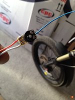
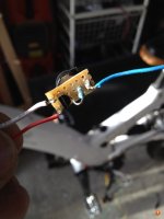
I'd been speaking to d8evh and he suggest I try the single transistor circuit as my controller has quite a low input resistance (about 1k) and was dragging down the voltage to almost half!

I modified the cct by adding a 10k potentionmeter from the supply (5v) to the base of the transistor so I could adjust the output voltage, as people have found out before you may put in 3v but only get 2.2v into the controller. The pot allowed me to adjust it once hooked up to the controller (ultramotor a2b if you were wondering) so I could get 1:1 voltage.
Circuit and some pictures below.

View attachment 2
 

Attachments

  • buffer2.jpg
    buffer2.jpg
    65.4 KB · Views: 2,874
  • buffer.jpg
    buffer.jpg
    57.2 KB · Views: 2,874
Rassy said:
Hi Hurty. This has been hashed over several times. The answer is a qualified yes. Whether brushed or brushless the best results are achieved when both systems are "identical". I.e. one throttle paralleled to both controllers, which are both wired to one battery pack of adequate AH. The motors and wheel sizes should also be the same.

I have done several projects involving either two or three hub motors running from a single throttle. I've done this with both brushed and brushless.

As long as everything is "identical" as described above the motors do not fight each other at all. In fact, I think they tend to help each other when accelerating or hill climbing, meaning the effect from the two motors is more than double that of a single motor.

Good luck with your project. :D

can you please help me
so if i have 2 hub motors 2 controllers 2 tire sizes all the same and if i split the power of 1 battery to the 2 controllers and split the throttol to the 2 controlles would that work
thanks
rj
 
Hi Jabro,

Yes. I answered your PM prior to seeing this, but what you propose doing should work. i.e., the two battery wires paralleled to each controller and the three throttle wires paralleled to each controller.

Of course your battery pack has to be sized properly for the total amps you expect to draw from it. :D
 
No. Don't parallel all the throttle wires. You only split the throttle signal wire to both controllers and use the 5v and ground only from one controller, leaving them not connected on the other.

You shouldn't connect any of the 5v wires between the controllers because they might be slightly different voltage. I think this might be the reason that people suffered glitches when they tried one throttle to two controllers.

It's the same with the PAS. You only need to double up the signal wire and connect it to the second controller. The brakes don't matter so much because there's a resistor between the 5v supply and the brake switch, but it's easier to use left brake to one controller and the right to the other.
 
I'm pretty sure that the previous reported problems were due to joining the two 5v regulators in parallel. I used the method I detailed above for my last 2WD, which worked perfectly. It's the simplest solution, so try it first. No harm will come from it, so nothing to lose.
 
Hey guys,

I realize I'm resurrecting sort of an old thread here but I'm working on a project and felt it would have been a little silly to start a whole new thread.

Basically my question is: is it wise, or even possible, to link two hub motors of different wattage to the same battery? My project involves a lightweight electric motorcycle being propelled by a 1500w hub motor in the back for now (I've so far only built the rear wheel), and I'm wondering if it would be possible to build a 1000w wheel for the front without having any problems. The idea is to use a LunaCycle 48v 20ah battery to power the rig, which says that it will produce 50 Amps continuously. According to calculations, that ends up being around 31 Amps to max out the 1500w rear motor. The reason I'm thinking of doing a 1000w front is so that I can use one battery to power the whole thing, and give the motors a bit of a nudge for each other to get going. I've read back in this thread seeing that people suggest having "identical" parts when running dual hub motors which is the reason I ask this. The other alternative is to do just that, and lace the front wheel to a 1500w motor, but I'm reluctant to do this as it will shorten my mileage and not really give me full push on either motor. Obviously I realize I would need independent controllers for each motor, as well as linking the motors to the same throttle. I'm mostly just looking for your guys' thoughts on a 1500w/1000w combo Vs. a 1500w/1500w combo given the type of battery I'm looking at.

Any help would be appreciated!
 
I'm not sure why you think using two 1500 watt motors would be less efficient. The watt's required to move you at any given speed will be about the same whether you have one motor, two "equal" motors, or two "unmatched" motors. The main variable will be the additional weight and friction of the second motor. And you have already read in this thread that two unmatched motors will not behave under certain conditions unless you have some intelligent balancing controller such as Kingfish used.

I also didn't quite follow your discussion on amps as it relates to the battery. The motors will accept whatever amps the controllers feed them, up until the motor either destroys itself or overheats. Likewise, the battery will attempt to supply whatever amps the controllers want up until the battery either destroys itself or the bms cuts out, etc.

In short, I wouldn't attempt to use mismatched motors or controllers, and I would make sure the max rating of the two controllers (added together) did not exceed the max rating of the battery.

Good luck with your project. :D
 
Ukiah said:
Basically my question is: is it wise, or even possible, to link two hub motors of different wattage to the same battery?
See both of my projects linked in my sig, CrazyBike2 and SB Cruiser.
 
I made a wiring diagram for a non-identical 2wd set-up and using a CA V3 with a single throttle here.https://endless-sphere.com/forums/viewtopic.php?f=2&t=71073
 
Alan B said:
You don't need to match the motors in power, but it is easier if the motors match in Kv, or RPM per volt. That way the same throttle signal will generate about the same speed on both wheels.

I've only done the setup once, so it's with only limited experience, but it did work as I expected. To me "about the same speed on both wheels" doesn't cut it. While I used motors with the same Kv, I felt it was important to avoid oscillation between which motor was pushing/pulling the bike, so I run a somewhat larger tire on front. That way regardless of how hard the rear was pushing the bike, the front was always applying positive torque. Due to limited traction up front under hard acceleration, I run that motor at lower current levels, but at any throttle position the front is always "trying" to go at a slightly higher ground speed than the rear, so it's always applying positive torque to the frame.
 
Using a lower current setting for the front motor is a good way to limit the MAXIMUM torque of the front controller. Of course it doesn't guarantee the torque relationship at any given moment. IN FACT,

Using a larger tire and matched Kv motors and controllers fed with one throttle will bias the motor speeds so the front motor will have MORE torque than the rear motor, AT ALL TIMES right up until the front motor torque limit is reached. That would not be what I would want. I would prefer the front motor to have torque proportional to the rear motor.

Feeding two controllers with one battery is both good and bad. They see the same supply voltage, which is important. However the controller grounds are not at the same voltage except when they are drawing the same current. As folks have reported here, if they put the throttle on nice and slow things are fine. But if the throttle is hit hard from zero things may oscillate. It may or may not happen with a particular setup, it depends on a number of variables, and just because it doesn't happen at one point there's no guarantee it will never occur. Let's step through what can happen.

First define the proper hookup. The controllers are close together and fed with a common cable to a point as close as possible to the two controllers, where it "Y"s to each controller with the minimum length of cable to minimize voltage drops between them. The throttle is fed from the primary controller. Ground, +5 and signal. Just the signal wire is "Y" connected over to the secondary controller's throttle input. Don't connect the two controller's throttle connections together at the rest of the throttle cable connections - the throttle grounds and the +5V connections should be kept separate. Connecting the two +5 connections together won't make much difference due to the diodes in the controllers, but connecting the throttle grounds together could lead to large currents flowing through these connections and they are not designed for that.

The primary controller always sees the throttle signal directly. But what does the secondary controller see? The battery current flowing to each controller raises the ground potential of that controller by I times R where I is the battery current and R is the resistance from the Y through the wiring and connectors into the controller, through the shunt and solder joints and circuit board traces to the microprocessor's ground inside the controller. Let's say the resistance is 5 milliohms, a fairly small value. If the battery current is 30 amps this makes a voltage drop of I time R or 150 millivolts. If the throttle range is 0.5 to 4 volts this corresponds to a physical throttle shift of 150/3500 which is 4%. So when the primary controller kicks up to 30 amps it will add 150 millivolts or 4% to the throttle value that the secondary controller sees. This makes the secondary controller attempt to accelerate even faster than the primary controller did, so its current jumps up and the current to the primary controller falls off as the load shifts to the secondary, and we have an oscillation due to the long throttle time constants in the controllers.

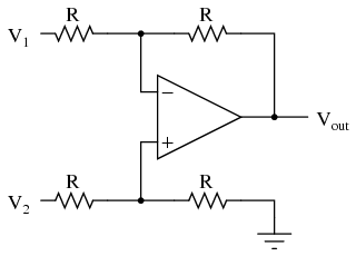
It doesn't always happen. Folks have solved it by putting two separate sensors in one throttle, by using two separate throttles, or it could be solved by adding a difference amplifier at the throttle input to the secondary controller, here is a simple example:

03044.png


The difference or differential amplifier re-references the output voltage to the ground at the output side. So the grounds moving around with respect to one another don't have any effect on the value the secondary controller sees. I can think of about half a dozen ways to accomplish this.

But there are too many variables to predict exactly how a particular system is going to behave, some real testing is required. Try it and see.

Using tires of different sizes is one way to attempt to bias the system slightly, but some resistors are easier to tune and cheaper, plus they provide more range of adjustment. Controllers don't have exactly the same gain, and motors of the same construction don't have exactly the same Kv due to physical and magnetic variations. Tires wear differently, the rear wears about three times faster than the front, so the bias will change with wear. It also changes with weight distribution and tire pressure.

A better solution is to use torque based throttle controllers. Then a small variation in throttle signals makes a minor torque shift and the system is much less sensitive. Then you can establish a true torque relationship between the two drives by adjusting the controllers, and we again find that PWM throttle based controllers are a liability for good control and performance on our ebikes.

Making an AWD ebike isn't hard. Many people have done it, and many used mismatched components. Perfection is not required. It tends to work best when the system load is higher, then both motors can more easily contribute. When system load is very light one motor can do the whole job and it requires more accurate balance to spread the load, but in that case one motor can do the job anyway, so the second isn't really needed.

Let us know how it works out, it is always interesting to see what problems do (or don't) crop up.
 
Alan B said:
Using a lower current setting for the front motor is a good way to limit the MAXIMUM torque of the front controller. Of course it doesn't guarantee the torque relationship at any given moment. IN FACT,

Using a larger tire and matched Kv motors and controllers fed with one throttle will bias the motor speeds so the front motor will have MORE torque than the rear motor, AT ALL TIMES right up until the front motor torque limit is reached. That would not be what I would want. I would prefer the front motor to have torque proportional to the rear motor.

Torque is based on current, and only at steady cruise could the front motor ever be producing more torque due to the lower rpm. I shouldn't have used the wording "torque on the frame". The goal was to always have the front motor applying positive thrust despite running at lower power. In that respect handling would be like a front wheel hubbie bike with very little power demand on the motor. The purpose is to avoid an odd feeling oscillation between which motor is propelling the bike at steady cruise, which seems possible to me with same Kv and wheel size front and rear. Maybe I'm wrong about that possibility, but the different size wheels works exactly as planned, and the resulting lower gearing of the rear makes it more capable of the much higher power sent to it.

John
 
Regarding wiring 2 controllers and one throttle. I do a lot of 2 controller builds to run my 6 phase motors. I tune them to get current as identical as possible, but there is a 3° timing offset. I've been toying with the idea of tying the low voltage rails together directly, or maybe even powering the low voltage sections from just one of the controllers to prevent voltage difference issues. Are either of those good ideas?
 
John in CR said:
Regarding wiring 2 controllers and one throttle. I do a lot of 2 controller builds to run my 6 phase motors. I tune them to get current as identical as possible, but there is a 3° timing offset. I've been toying with the idea of tying the low voltage rails together directly, or maybe even powering the low voltage sections from just one of the controllers to prevent voltage difference issues. Are either of those good ideas?

I'd be concerned that, when there is a voltage difference between the controllers with tied low voltage rails that large currents could flow in this connection. It could have undesired side effects. Is there a problem that needs to be solved? Are the battery current flows balanced between the controllers?

I saw one AWD build where they re-packaged the two controller PC boards and physically bonded the two input DC connections so there was no cable and no connectors between them. It worked on one build and not on another (to avoid oscillation), so even that was a little hit and miss. Of course even bonding directly like that doesn't remove the shunt resistors and circuit board resistance from the equation.

In fact, as I think about this, interconnecting the internal low voltage rails is potentially going to confuse the shunt readings. It depends on where they place the shunt in their design, it would be best to look at the actual schematics of the controller and see, but the shunts likely sit between the DC input ground and the internal low voltage DC ground. So the shunt itself is contributing to the ground differential voltage. Connecting the low voltage DC grounds together would attempt to average the two shunt readings, but to do that fairly sizeable currents would have to flow at these low impedances.

It might work, or it might cause some issues. Hard to predict with everything that's going on plus the unknowns. I would let them float and make an external circuit that provides each controller with the same throttle signal (with respect to its own ground), and allows some individual tuning. But if you do try it we might learn something from the experiment.
 
6yiaGY3JLZeBzjpg6WQG-CBjkxLHZwOjY_XTJ3w1vyIpEPu5gh6oI_K_DQF8UW9N3w5WX1B5qTZ343ePK8LGNNttXowlbKaF5vm1pZPsiiFvRNgOF3J9hJo9ZCG5P0IgVHee82sHbqf6k3Y0n64edDfptIrRbVEGN7J6yj5LGz5OtHQqihP2f_4oQwLjxlKP0hBDjrLaP3ENqzrYA9nRiXuyvM-TjAyxthoZY-pbXfSHK9tno1ziR4zmUHwiOtXCxQ0NQtWR-mblCHdWz9GmFnpWMxsj7-9h-VAKF8j-lECAV6bLouV8rHa8ls7rJsh8kBYuL_muOOxTE8tuxWhGau4hrToh3f4FUcTdd9TSfYAJpuEcQUhFkjJb6sY8Etagpco1qO963DqP21JdHbam-Fd2Z-5wsYPoDNfRwQXgwsPC0dJVM8GwU68dNwI51hZ8nydG9XqSKjwv92OuRamr3diweDnDm0mOnBcmwYqZLepBgeDit3axe-iYa-ryzdXpMdiLa1AdVrcKGV7QLqqlBm_bHN_SCR3PH-hFE2NF3lu3TgkFcc1cpk38_uCEcw2e4WUnjg=w561-h705-no


Above is a small pc board (about 1 square inch) I designed yesterday that implements the circuit I showed earlier. This throttle buffer or throttle splitter takes three connectors, one for each controller and one for the throttle. It connects the throttle directly to one controller, and through a 1:1 differential buffer amplifier to the other controller. This produces the same voltage to both inputs even if the grounds are at slightly different potentials. This is a simple circuit but it will maintain a precise copy of the throttle signal to the second controller re-referenced to the second controller's ground with up to half the throttle voltage difference between grounds. So if your minimum throttle is 0.5V then it will handle 0.25V of ground difference when the throttle is closed, and more when it is open. This level of ground difference would normally make a fairly large change in throttle. With 40 amp controllers E/I equals 6 milliohms between the controllers. This represents about 6 feet of #10 wire's resistance, we should be able to do better than that.

This circuit has no adjustments, it is precisely 1:1. I'm going to look at some designs for a version with adjustable gain and offset.

If there's interest we could have some pc boards made.
 
Haven't seen the schematics if it is a problem or not, but I think your ground plane is broken in to two unconnected pieces on the above PCB.
 
Thanks for the feedback.

Looks like that but the traces take care of the circuit, the groundplanes are poured in addition, on both sides. It passes wire checks and design rule checks so it is probably ok. Not sure I'm going to make any of these, if I do I will clean it up a bit and check it thoroughly.

It is more likely that I would make the version I'm working on now, with gain and offset adjustments. Then both motors could be tuned for equal speed at both ends of the throttle. Or slightly unequal, whatever is desired.

But the version I really want to make is different, digital, and will do even more.
 
Back
Top