Bonanza "Bulldozer" Dual PhaseRunner AWD

One element of this project is a Throttle Manager that will control the two motor controllers and share the load. I've been working on this part lately, so here's an update.

The problem is we can't feed one throttle to two controllers and have good sharing of power and torque. Even with matched hubmotors there are problems, and we don't have matched motors here. The rear is a Nine Continents DD and the front is a BMC gearmotor. Their effective Kv's are similar, but they are not matched. Even with the same motors the controllers have variations and their grounds are not at the same exact potential due to the large currents flowing through the controllers. This makes their readings of the throttle differ, and change with time and loading. Others have reported hitting the throttle hard on a dual can cause galloping, or oscillation between the motors, or cause one motor to do everything and the other not help, while increasing power gradually avoided this. This can be understood by looking at the current/throttle apparent voltage as the "grounds" of the controllers shift with respect to one another while looking at the one throttle, causing their throttle inputs to shift.

We already know from experience with other controllers (such as the Sabvoton on the Borg linked in my signature) that torque throttle response is more desirable than the usual PWM throttle that the Xie Chang type controllers (and most other ebike controllers) give us. This becomes more important as the power level is increased. With two motors this ebike will have more power and be even more sensitive to throttle. So we want torque throttle response.

There are a few ways to get that. One is to replace the controllers with models that have torque control built in. There aren't too many controllers available at this end of the power scale that have that (especially low cost controllers). One could buy an Adaptto, they have torque throttle and AWD controls. But that is a significant investment and support and availability in the USA is difficult thus far. The Ebikes.ca BAC units are a possibility when they are more available (or out of beta), though I'm not sure how well they handle the gearmotors.

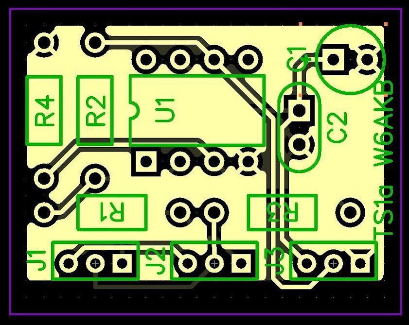
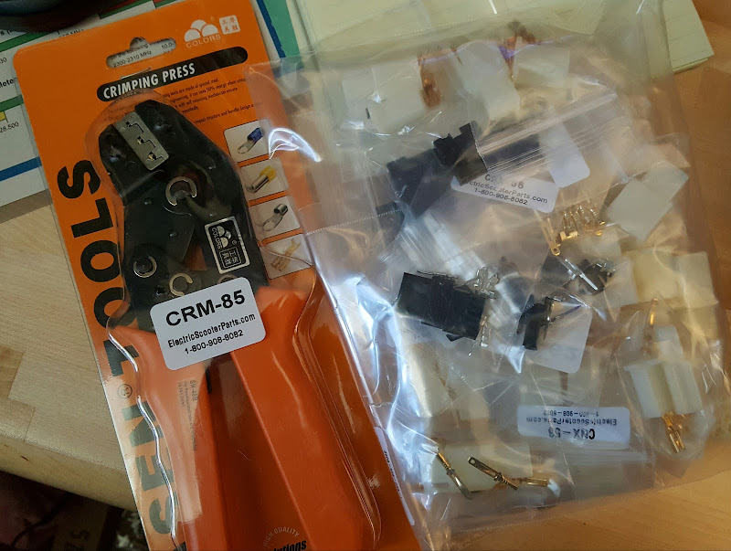
So I've been looking at what it would take to build a small circuit board that would perform both functions (torque control and throttle sharing) with a small Arduino type processor. Here is a similar one I built for the ebrake circuit on the Borg:

ENownhQo0j6BsqCyd0cz5Qc7FVRQbCaDca6GdgROWLVvBNvth04OsKjG26_P3N3zvZf4-oaNM3M16v8BqbJnB7wHCkMf9hfN__8N9pMw_2zVsXBfQKfD3NGppJz8oauQ7l20qL-3M6wqhqnUMNhtwm7KJVngU8ilyODlyKsJ_ivhcGT-TOFX7cb9i6djLJY9vP8jZ7kPKYY3bHpSo8LKvv6Kzt4kiwM23gD0VE7luT0ftpg8NnU4L2K_mqIoQ3CJLUpi-eYGb66MvhoKLWxfFvUFGsOQhwL2pPGssE1Bse2Q0UkWeDeRVacE07NrEQIcW1OZUByfrgg5qymXrjTx2hKNQrbqOdKfymh2bH5mtd9RPfNT-4yY_aX7kN8azkGXpLVZECacgsRy6XQp0vww2fLYB61GAi7pAmydr3g71nKxthAMrjYXRIvx5Qpabcc3xLYliP1htMElevj43MVpPdgMDLWaW8cBSDv8KGMl7Eh0nEowol3lolwN7mcVR12QNOEy9fKZEDdx0IUBOgYIE1hxh-w7HUiXkLsDom_es74bxVE2LyvFbbgz_1RRLSumdtCqRg=w499-h319-no


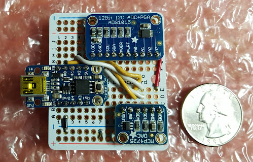
Above is an Adafruit Trinket with I2C ADC and DAC for processing the ebrake signal on the Borg, it is built and programmed but I didn't deploy it on the Borg because I found a way to adjust the controller parameters and avoid the need for this device, but it could be deployed for any project that needed a 12 bit multichannel ADC and one 12 bit DAC output. It could be used here, though it is a bit smaller than I'd like for what the throttle manager will need.

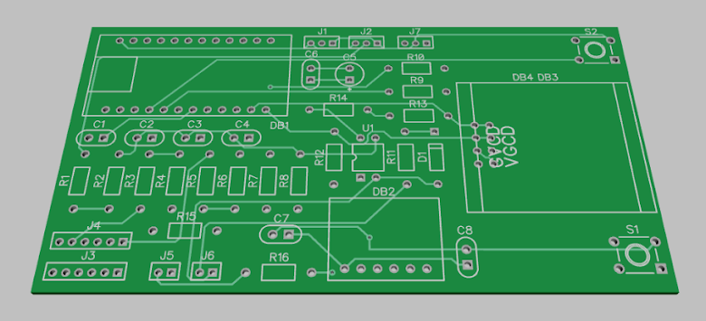
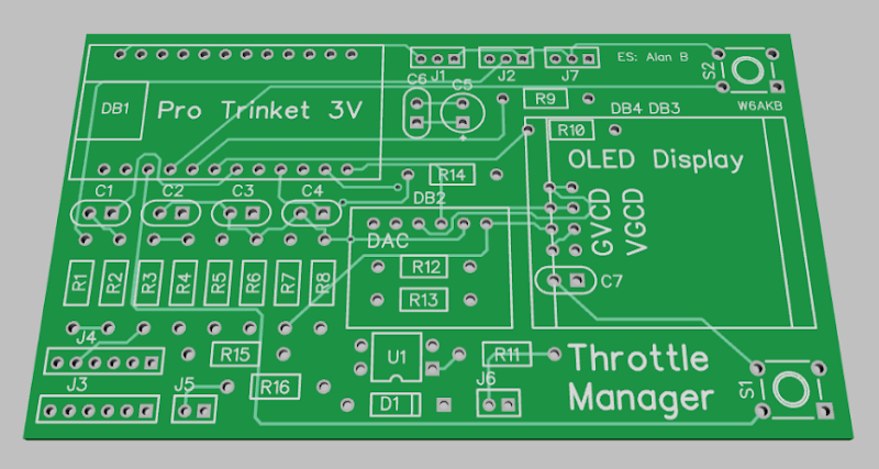
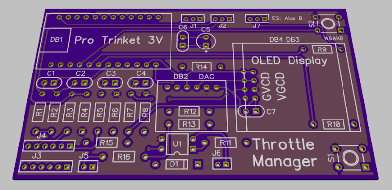
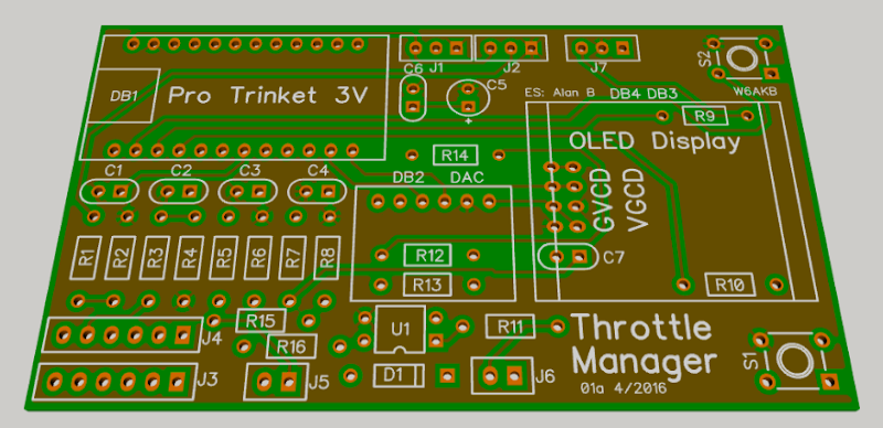
So I'm looking at using a slightly larger chip for the manager as I need more I/O and want a display for debugging and configuration:

IpwHf5CiWdX684W1WEPIyLMjpcMrZNlnrDMfsYjvzkmR72d52HnvDXlJi1rYayK3o63K0phPGRUvLLtKpddy8pXW1rBf7DUwXCcu0XSTUqhGqLop7M5A_3eGlNyxVbjKzBfedsDdvdnW1HBh7Su85TK-EzYqR2BlFCT4Gi-mn_4BRjQ7j1Wwcd2EmELuxpfevvPdhKsp6X7EIx6RhIwBtzDS8xNaUYOwoxvnsdDSGsngsour5N7isk2bHro7SSIc12Q3RxeCWyuLOyT5P-2b1Mo8zT0aJwldA7WSTdxS22k9YMUn1xGvb76r-Q50msE2_K99NhabyD_-Jy60EZjPmwcTL0H1xmcwR9cHlaj-7YZ9hQtZQGcmQkSnmxcGSddkA6KC36bbt1qzxFFujIhyjr58JwtH41PAp2opy0f8vuB1QUGth-elWSIDpxghLrB4WEVsbo9N4tXmH-mNmwrmbccw1QXSOyRVH8iy7IgY7SYxcRu2KZmF2tz3BsZ4JR6nl5gkfJVMaG1Id8Xc4gDqNzXmdqTGrF5Jhtj8Z0fIh2JzO1nQNemBf_3Xq2kapzdr_chQjQ=w546-h319-no


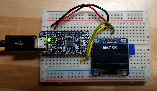
So this will be expanded with an ADC and a DAC (like the board above) and programmed for Throttle Management. I've talked about the algorithms to do this elsewhere on ES, but a real test is required to determine if the theory works well enough, or if the simplifications and assumptions made are accurate enough to produce a good torque throttle. If that works a simple extension to a dual version can handle the AWD in a nice fashion.

The additional problem is the gearmotor. To avoid slamming the gearmotor clutch will take some extra finesse, but that should be possible to add after the basic design is working.
 
Alan B said:
One element of this project is a Throttle Manager that will control the two motor controllers and share the load.
If you get this working, then depending on cost and ability to bypass instantly with a button at need, I'd be interested in "beta testing" a version of it for the SB Cruiser trike. (keeping in mind that I'm not much of an engineer and know just the basic idea of programming, from long ago).

It has side-by-side mismatched hubmotors and controllers, for the two rear wheels, rather than tandem like your bike and CrazyBike2, so while it is possible to mostly control the steering while hitting max power at startup from a stop, for instance, it is still a bit disconcerting even after so many months of riding it under various conditions.

I suspect my side-by-side use case might be more of a challenge than the tandem usage, and might not be possible to do (at least not simply), as I do need independent control during turns (with the outside motor providing more power or all the power, depending on sharpness of turn and speed).

Also, braking on mine doesn't really do regen, but it has "EABS" that is MUCH more powerfull on the rightside motor/controller than the left, with no way I can find to adjust them (would like to make the left one match the right, for more braking). So it pulls hard to the right when I use EABS, less so with Yogi in the trailer drag-loading the system but still does it.


Someday I'd like to make it 3WD, too, with a geared hub up front; dunno how much it would complicate things. :)
 
Good questions Amber,

Torque throttle control will help a lot, each motor will be pushing with the same torque regardless of speed, so the power will differ as the speed does. The speeds of each motor are unrelated as the manger tracks the speed of that motor and adjusts the PWM to get the desired torque. Thre is no harder than two the way I'm planning to do it, the throttle just gets passed to each manager and it provides that value.

If a different level of torque is wanted for left and right wheels that would be harder. But hopefully not necessary. It might become important if the weight on the inside wheel unloads it too much. Perhaps an accelerometer would be useful there, to reduce torque to the inside wheel. Might not be that hard to do.
 
The main reason I would need more power on the outside wheel in a turn is that I've found unless I reduce or cutoff power to the inside wheel, I cannot make a very tight turn at any speed--but if I do this, and engage the power to the outside wheel only, at just a bit into the turn, I can make a fairly tight turn at a fairly high speed (relative to the top speed of just under 20MPH), without tipping the trike.

If I don't depower the inside wheel until I am most of the way thru a turn, at least, it will push me into a wider turn, which means either:

--I have to slow down enough that a car behind me might clip me (some simply won't slow down for another vehicle that is turning out of their way, even though only a fraction ofa second might be lost by doing so, and in fact may gun their engines to go faster!). It's not that common an occurence, but it could happen at any time I'm on the road turning at an intersection.

--I will end up at the left part of the lane I'm turning into or even the right part of the next lane over, neither of which is a good thing.

--I'll tip the trike up on two wheels, with the potential for flipping it--which thankfully I've never done on this trike, but I did it more than once on it's predecessor, Delta Tipper...er...Tripper. ;)


Aside:

I don't know if it's adaptable to this purpose, but I have one of the version one STM32 Circle units, which I initially picked up at a seminar (shortly before I found ES, I think) to try to learn MCU programming and use it as the "brain" of a complete ebike control system (motor, bms, lights, turn signals, eabs, detecting gearshifts and braking and tilt (to turn off the motor past some loss-of-control point), etc).

But I am really not a programmer, and I guess I just don't think the right way to do that sort of thing; I never was able to learn the language. I did learn BASIC as a kid on VIC20 and Apple ][, and machine code at DeVry, but I was never very good at any of them despite being fairly creative at my applications, and ways of doing things in the programs, they didn't work very well and were huge and clunky at best. :oops:

I was never able to attract anyone interested in collaborating on the project either, though several said they wanted to, none ever got back with me or responded to any communications. I posted a thread about it on the Adafruit forums; it might still be there.

pokepokepeekpeek...yep, still there
http://forums.adafruit.com/viewtopic.php?t=7346
Nowadays I'd have some different requirements for it, but I'd still like a lot of the features it would have had.
 
Hi Amber, hardware and software has improved a lot since 2008, for example accelerometers are cheap and ubiquitous with lots of chips made for cellphones etc. I've bought a few but not taken the time to use one. But it is easy to imagine lots of features, and the complexity quickly grows. It is best to pick some core feature, figure out how to do that, get that working, and then expand it. You will find people are willing to give advice or help on a piece of it, but they won't want to take on the whole project, you need to manage that.

In this case the phenomenon you are experiencing with the trike turning is due to the PWM throttle characteristic of the motor controllers which are emulating a fixed solid rear axle between the wheels by applying the same constant voltage to the two motors which attempts to operate them at the same RPM which resists turning. Torque control changes this, allowing each motor to apply the same torque but allowing the speed to change as is required by the turn radius, which is like having a differential.

But I need to make it work for one motor first, and keep it simple for success. Then I can expand it to handle a gearmotor's clutching issues, then on to two motors from a single throttle. If it works on my 2 wheel drive mountain bike it might also work for your multimotor trike. If it doesn't work adequately then a pair of PhaseRunner controllers might be the next step.

Controlling the torque instead of the speed makes a major shift in the controllability. Justin indicated he found a five or six times reduction in control sensitivity or gain with torque mode, and this factor grows with motor power. If we can do this easily for inexpensive common controllers it could be quite useful. It is a game changer. I have it on the Borg via the Sabvoton controller, and it changes the ride from a jerky hard to manage throttle to a smooth easy control, not unlike a Zero electric motorcycle, at least from zero to twentysomething mph. It is like you are being towed via a spring, and the throttle smoothly controls how much force the spring is exerting, whereas a PWM throttle is like being towed by a chain and it jerks and yanks you along.
 
Alan B said:
But it is easy to imagine lots of features, and the complexity quickly grows. It is best to pick some core feature, figure out how to do that, get that working, and then expand it. You will find people are willing to give advice or help on a piece of it, but they won't want to take on the whole project, you need to manage that.
I suppose that might be true, but I am not much of a manager. :oops: I'm one of those "idea people" that has lots of ideas but not much practical way to implement them (or rather, not much ability or knowledge to implement them, just know that they are easily possible with the right stuff). I suppose if I had enough time (didn't have to work a dayjob to survive) I might eventually learn enough to do stuff myself (or find the right people to do it).


In this case the phenomenon you are experiencing with the trike turning is due to the PWM throttle characteristic of the motor controllers which are emulating a fixed solid rear axle between the wheels by applying the same constant voltage to the two motors which attempts to operate them at the same RPM which resists turning.
Does this still apply even though I have two totally separate motor systems, each with it's own controller and throttle?


Torque control changes this, allowing each motor to apply the same torque but allowing the speed to change as is required by the turn radius, which is like having a differential.
Ok. I follow that, I think....


But I need to make it work for one motor first, and keep it simple for success. Then I can expand it to handle a gearmotor's clutching issues, then on to two motors from a single throttle. If it works on my 2 wheel drive mountain bike it might also work for your multimotor trike. If it doesn't work adequately then a pair of PhaseRunner controllers might be the next step.
I have one of the older versions...but not two. (and no budget for that...so if that's what's needed, I'll have to live with the present setup).


It is like you are being towed via a spring, and the throttle smoothly controls how much force the spring is exerting, whereas a PWM throttle is like being towed by a chain and it jerks and yanks you along.
I guess my stuff must just be so heavy that even with 3-4kw on tap I still don't have that jerkiness (or I am so used to it that I don't notice it).
 
amberwolf said:
Alan B said:
...
It is like you are being towed via a spring, and the throttle smoothly controls how much force the spring is exerting, whereas a PWM throttle is like being towed by a chain and it jerks and yanks you along.
I guess my stuff must just be so heavy that even with 3-4kw on tap I still don't have that jerkiness (or I am so used to it that I don't notice it).

Exactly, the load to power ratio reduces the jerk rate, but both controllers are putting out effectively a constant voltage, and then each motor is trying to reach the unloaded speed appropriate for that voltage, and any slowdown creates an increase in power and torque. So the torque jumps all over the place as you hit variations in the road, or try to turn, and the motor does its best to counteract the turn. With a torque control the torque would stay the same, and the speed would merely shift smoothly, so it would not fight the turn. It is very different. The only time it is a problem is if the wheel slips, then it speeds up trying to deliver that torque, and spins. For that case we can add a speed limit term so it doesn't speed up too much.
 
Working through the Throttle Manager design. Prototype hardware is trickling in. There are still some problems to solve, but looking good so far. Things always seem to get more complicated than they should.

The board will be fairly small. Hopefully we can borrow enough 5V power from the throttle line to power it. I wonder how much we can get there? It won't need much to operate, the user interface might take a bit more, but only when setting it up. In that case a small battery could provide it. Or the Cycle Analyst perhaps. One of these days I need to build some high voltage switchers to make 5 volts.

The Throttle Manager will connect between the throttle and the controller, and borrow a couple of signals from the Cycle Analyst connector. So it will have a throttle input and a throttle output, and a Cycle Analyst input and output, though those will be directly paralleled as it just needs to borrow two signals from there.

It will have to be calibrated against the motor. I'm working on easy ways to do that.
 
nG4o6udiowcd05wNoSxT87R97TPmFkQkvVLxpjR00OwTxg0r91WgjCOXJes1F81OMNDXVsCRmKoP7DShnK3VThy-aWnss-PTs4rMH8UCx6-TrM5St3Dhxb2scb9gbGnjAuXZldA23NSUeNSJrB8aD9Enlqydf7yh-1dHXQs5CreVS8LstUCKNBAJvlMdtnvB3J5hMLkz2gpm82WFkMQuOkFbg49Hns-nM8BmyTRcRpQT2YXBR0gzZ5x_Ok7Gvus-IWi7ttY8IxcbDmGH69pUiq4AbOo4wBsujlL6qVgUAnnG1JtFW-nT-foVtIZqHTqVRuRc4glFuJonFfOodG77TW84Ju_2c41GzSK2-Lhq91vXoXTQqv0jHkV8iHD9UsH8VOTgz2HdIHmMMqY_JSMJPzXT1iyEjBhUZhUdBnRk1DJkMAAyLKgCW1AAMsOBRH_l4s1NeoAaK7pQMpA5nRaxrG8B_0t1ti2srri8wEQqmMFkze5Cvn6tSAx_5e-fxl-dxMll4y3uYPL3o5S79EcUeC5MiEWY3iY1zwGPm333jyZ7DzT-RnYe2Wk9ZjZI4m-NmS1cGA=w841-h669-no


03044.png


This is one approach to using two controllers with one throttle. The classic Differential Amplifier. The output voltage is the difference between the input voltages, in this case V2 minus V1. So you wire the throttle straight through to one controller, and you use this circuit to make a copy of the throttle voltage re-referenced to the local controller ground. This should work for the same controllers and motors with the same Kv. Both will get the same throttle voltage even though the grounds shift a bit. The amount of shift this circuit can tolerate is half the minimum throttle voltage. So if your minimum throttle voltage is 0.6V it will tolerate 0.3V of ground difference.

The circuit board shown is about one square inch, it is much larger than life in this screencap. It is a quick DipTrace layout as I'm refamiliarizing myself with DipTrace for some projects. The new 3.0 DipTrace Schematic and PCB software is very nice.

We could make some of these boards but I'm moving on to designs with more features.
 
I spent some time on the analog design and didn't like the results. Adding the gain term is easy, adding a bipolar offset term not so easy. It got messier than I want to deal with.

I took a look at a different approach. The digital approach:

gEnGbrkcdX6pgVWcqj7R0iEDAEwZoWBzZ5z2A_gjhM1Up4FmifvxB1fAw7efcbpU44QSeyofxUvWe-mVFjL4IUZDxwPRPtU-lQAndNW81TEYptSAvhS8HBHfmbFO_uIIyGJ5wOs3iR1FirrTym0gW07lzUbTASu1Tl6BpXPNmGqBylz53vdsxxUSf4MbS4N4pkKlE-NGMic9xqpMkuf0YZH7YvqF45JKYRW7rMQ-n1-VHwanvaXvJDeRW-1FhBV8AT-bfMB6EM1vP8qXoVuCt-SSOUR5p6SBONvifMS_YNJn-ZtYcgnCK0I6A2BOEHZxtI_oDzgGp1_2WuN4VB656axVNfY1BIQOPxgy5deFgO_gEuW4e_bbs9uBSHHhvCC97vt6DnOlf-qGPNMPnuxzYYFm26CkkPIcUQShIXBHff1uSfH6DKCCifz2bLbSV2xLArZ97LU6-ms0SRu__clCA--qHA_DFkurcdOddietKC2tLLSU7PTn3l6ZlUkQcUNfaHApxlOD4sw1NxZ_SEuJo--adDnYmtFoF7cdjV0CPxsQilLMtKzB2Y0g_PlpeQI1wvbq7Q=w541-h669-no


So here we connect one throttle straight through to the first controller, and on the second controller we use a small micro (an Arduino would work) and read the throttle voltage, and a couple of potentiometers that can be used to set the gain and offset we want. The result of the calculation is sent to a DAC chip to convert it to the analog voltage to drive the second controller.

The only thing missing here is the differential part, and we added that too. There's a resistor/diode that generates a voltage offset 0.7V above the first controller's ground that we also digitize. We can see from this reading whether the ground has shifted and by how much, and apply that correction to the throttle signals. This will handle up to 0.7 volts of offset, which is more than the analog circuit (shown earlier) and should be more than adequate.

The DAC could be replaced by PWM but that would require a filter and a buffer amplifier and it would add noise and lag to the throttle, these little tiny 12 bit DACs are very precise and easy to interface. Adafruit sells them on a small breakout board that makes them very easy to wire up.
 
The goal of the throttle sharing buffer amp above is to match the two motors and controllers speeds over the throttle range. By adjusting the Offset control we can change when each motor starts turning, we probably want them to start at the same throttle setting. The Gain control is used to synchronize them at the high end of the throttle, so this can make up for different motor Kv or tire sizes. You can adjust them to the same speed, or you can adjust them so one or the other is slightly faster if you wish.

It is best if both controllers are fed from the same battery, otherwise the changing voltage on one will be slightly different than the changing voltage on the other, and this will shift the speeds of the motors away from the match that you are trying to achieve. With the same battery feeding both they will shift together.

There are a lot of other things that can be done in the CPU, for example it was suggested that I drop the front motor out at higher speeds. Since throttle settings are speed related this could be done in the software.

Protection for an open throttle ground could also be done in software, at least for the second controller. If the throttle signal is too high this should trigger protection and output 0V.

This software needs to be reliable to be safe. It is a simple program running a tight loop, there is no operating system. Software like this can be quite simple and reliable. There is also watchdog hardware in the CPU that can be engaged to automatically restart the processor if it ever fails to run the loop.

One other concern is the power up state of the DAC. If it powers up at some random voltage output value this could start the motor before the CPU has a chance to set it. This DAC has onchip flash memory that you can program with the default value, so it comes online with this value rather than a random value. Set this to come up at zero or some low value that doesn't cause any motor motion.
 
MzX8xGZQCIE0TO0_eW5wOX8W6LhUW2wXJ6iTKiU1oSVVP6QoomEBlMoongFM-h6n6oOXFR3LC3b6ZZLkPJTN8-WL3cWFvglOrVKFioPH5nXBuALHTq5m7shXZJZMYdAr_EY_meqoaGPoW8XN9deba1lmq5Mm98WklCm9nHj_nc2gguY9jKMUyjsPMUCArA7RRnoOqCH35NVMZ-BAbKnknfvEgVJNr5xdVw0N8h3psgIePXHFjBAdkjexDrJ9Rzw6_aAIlicbhed65yS7Hrv1K4s34dIi23-t3YCMM1rVHVl8IHp0DeKPA6dzCDbNlCxLCz1bMt2RivNggV7mfx7tYoqm2HYfya8hREu18wpi3GuylvoPxe31choAqKVzl2esx1c1gYudPSmSxQuGuhf1AjxybAMSzpvm9dgPWfeeGFug2RCPO_HFv9qjGCZnA-urA1ExV3VA9gWkIE44VgZxGXrYynrY2zl2yPxfv0BPgGLNPrSR1ewhRl64p4zSXMsq1qt3aNpBae2ffiqFzCAj20V5v_qZ-zXOhWkcIWFryLS5o6N2mmjiXOeasUbqTas-VBOV_w=w800-h355-no


Made good progress on this design today. Input the schematic and parts for the Throttle Manager. Made a few major design changes to reduce the power consumption and parts count. Did a rough PCB layout and autoroute just to get a flavor for how big this thing is (this layout is about 2x4 inches). I could make it much smaller with SMT parts, but to make it easy this prototype is through hole parts and uses a couple of premade daughterboards - the Trinket Pro and the DAC. So it could be duplicated easily. I have two overlapping layouts for the display because they make them with different pinouts, and I have both, so this board will take either. I can see a number of optimizations to be made on the PCB, and there are more things to check, so this is not ready for production.

So what do we have here? We have a module that goes between the throttle and the controller, and it grabs a couple of signals from the Cycle Analyst connector (such as speed and battery voltage). Equipped with the mating plugs this will drop right into the cabling and can be quickly removed if necessary. It gets power from the Controller's throttle connector. It operates primarily on 3.3V so it won't be confused by the variability of the input power. It supplies whatever the controller provides to the throttle and to the ratiometric DAC that generates the output voltage that it sends to the controller.

It has a small graphical OLED display and a couple of pushbuttons for a user interface. This is planned to be used for configuration and error codes, it is not even turned on in normal use to save power. The display is only one inch but it can display a lot of information (128x64) which is useful for debugging and development. The low cost and I2C interface makes it well suited for board or small module level user interfacing.

So this is the hardware that has the inputs needed to make a torque throttle from a PWM controller. This same hardware could be used for a number of different algorithms relating to throttle management. Plus it has an optical link for coordinating with a second module for 2WD. It can be bidirectional if needed. More than two could be combined into a ring, each one taking care of a motor controller, if more than 2 motors are used.

Enough fun for one day.

Edit - correcting some details, and noting that it is now 6.5 square inches down from the original 8 square inches. Progress continues...
 
ylDXg5Xlzd9LwDDNbXMyRQFpgLzlj4CZZvGx9Iw_ZSLm4hP8ZGN_qNme9YGBGnTif9hiH9rPn_F4aGe0oDEjvZZ5kUr2ksKm7uXVVx9VcV9slZwKPPfLrsfFhsysfFioNz2BKnDVu8CPjzjp0YPxYnUS3QGzvs_i0gijM5sostUdY9-I_QVQFWk11_YzcP_oPfLnh8LUHsRVn-GTQmozF2ax5zESKO0uzQe4_07Qo3yU5biF0Fwvpl0GiJnL0g7PpBF8EASgFBk-jVSHik8ZkCcyFJos-sBJrO0qYEm2e83QyKJleEOE1SjzsGVNvBf0ESO53s6RkYuf-gSweUjKFEUudYYT-BYKRvcKiHZq4zm2j-Ql3HskwPpgHptV-mo1GJ6q1DRzkG701RdwGtVI0sxb376xgHETtz9_GrE_RqEAR4m_fnu7wUIBaAzCSGeEr6eT2qqLSWyw6i8xHlhPW8k0AdmyuU5YAa0Xe8rIr6177WmLs2BGLY8xVdbhNX4rCfk3HGhz8-KOqW8LmL-n3ukvsKiZ0fndJzPJUwgqYOkANonpyaMSk5gz9RK2MHY_ZMp1qw=w800-h430-no


Made a bit more progress today on the board. Managed to get it under 6.5 square inches (about 3.4" x 1.9"). Improved the labelling and checked a few things. Made checklists of what needs to be done, quite a bit to verify yet, and a lot of calculations to determine the final values of the components. As they say, the devil is in the details. Enjoying DipTrace's feature set while I re-familiarize myself with it.

I need to order some connectors from scooterparts so this will plug directly into the Throttle connectors on the Lyen controller. I need to make it easy to test and remove from the ebike. I already have some Cycle Analyst connectors from ebikes.ca in the useful little kits they have available.

I already have the code framed up, at least roughly, and most of the math worked out for the CPU, and a start on some documentation for this board.
 
law_of_ohms said:
I hope you can sell me one when done!

Just put 2WD on my bike, and yea, it really needs to be matched.

Hi Melbourne,

Welcome to ES.

If it works out as well as I imagine, it will be very useful. If not, well, we'll have learned something for certain in the process.

Today I spent a lot of time analyzing the component values and detailing some of the pseudo code relating to computing motor speed. It turns out that the algorithm I'm planning is sensitive to knowing the back EMF accurately, and to accurately estimate the back EMF we need good speed accuracy. If the speed value is noisy at the level of 1% the throttle would have 6% jitter (based on a particular setup). Which is exactly why controlling this by hand is hard, our input gets magnified by factors like 6 when controlling a high power ebike motor with PWM (Justin has mentioned this same factor of 6). We can filter it, but that introduces lag which we are trying hard to avoid. So I'm working on measuring the motor speed more accurately with some tricks in the CPU that don't introduce significant lag. There are also some counter overflow issues that have to be handled exactly right or the resulting speed might take a sudden jump every now and then. I also ordered more connectors and made a few passes through the schematic and board, cleaning things up and checking things.

So far the most concerning issue is this speed measurement precision and noise. If it turns out to be a problem, we can always add a little filtering, it is just a tradeoff between smoothness and latency. At this point there is just a very little delay caused by the differentiating required to measure speed. It adds a little noise and a little delay, that's unavoidable. But we have no other way of measuring speed, and we need it to get back EMF to make this algorithm work. But these delays are small compared to the normal feedback loops and filters that people use in their throttles so I think it will be fine. I'm probably over-analyzing, but I'd like this to work on the first iteration (of the hardware) and not have to cut PC boards a few times to get the kinks out. So I spend a little extra time up front, do some calculations, and think about it a bit before pulling the trigger. And I can't get the hardware right if the software isn't pretty well worked through, at least in a design sense.

The board design will probably not be completed this week, and this weekend I'm going to be busy with other things, so it will be next week. I adjusted the colors a little bit closer to what OSH Park PC boards look like as well, though they definitely look better than this with gold on the traces and a dark purple mask on a dark purple board. A Groundplane was added to the top layer and the routing cleaned up, both traces and spaces were increased. So here's the PCB progress:

OexP_Pf1o-Z7U6vmzgmDwnfqbStJ3IAEoP6KXoInyOmms2mQJ3Be0kPcj0wUXL4-ZLI1DYsXHx-yoAQlgj1zsD2Ade2oonRC_wPvM4yibUux6tLuA3SAa6t-HiVm81RsUnKzc96-yY-U0Z4uGupD3e3K4wY_XQi0sGdWZSRtUWhYbhxcjnzPNHYmgf2L9PVub41xsqu4ajMOtOijLXqnGkhf32zY-eVsp-LpB0wSsd5mkjynonjYLMpzmsgORrRabc9Qg-SO429hkmzFIi-C44UGkMgfIo2VbuWvmkfQG1aOlSQejkkh76ZTwdgI2LgCwgc7t7weXThxFE4ZQ-yDYibToKMRTPhxGg38DE7aXmVF9FJ5LZoUxgXbFNIarhWgCYLwvuhUduWv1gxU5FaJyZ41_2R30-QiqzJHfANNjbn_-7eIMDrJdzwshi6I6O7XVv-JsTtaTB-oBJ88xoCOnr-XN0-oQgAiwd6bfHELEHPASexmmPLVffw5pAJQXLuNPWwewwsl4fDT34HuCm7xaBg-vshSbklFs-VsZGkMQbdK_NjjV6XpUlVDzuVMiIp6jvL-nA=w800-h400-no
 
Today started out very frustrating, with autorouting failing constantly, whereas before it never failed. It took awhile to find the problem, which I think is a bug in their software, but with the workaround in hand I was able to go forward. As with most workarounds it was easy enough to do once the answer was discovered. Just delete the groundplane copper pour, and do that at the end. Which is fine, I just wanted to see it earlier and then set it to not poured, but the autorouting seemed to get tangled up by it even though it was set to ignore the pour. The autorouting didn't fail right away, which made it harder for me to relate the change to the problem. After that things picked up considerably.

I went through the verifications of the layouts, pin usage, hole sizes, and fixed a bunch of small things. I had to rework a lot of the layouts a bit for the larger holes, and the board a bit for the resulting changes. I did major cleanup on the autorouting, and retired all the vias.

I added quite a few checks to the list, and completed them all. The board is ready for production, I've already uploaded it to OSH Park. But I will inspect it a bit more before I pull the trigger on the prototype board manufacturing. The production will take a couple of weeks. It is design #10 with OSH Park for me, and most of those are ebike related boards.

So if there are any comments relating to the PC board, now is the time to make them.

ip2ewSVqlZUWtXbCzFfeEXh7bIu3eT2dEBuwOeTD0zks8WscFAruBpFahl2-STZNZOch9ceehCGwJ8igw618e-Bjpl66kVvl52etqmst_JVJjD3EB3rP0B0bAmCZdx-Nfkh_qd0u9rzGO5bkCCrIKh2X8b8pYwV8iCiVvnQUiDRchyaHKTT5qUxx13610qyZlgJAuzKKq8WE50kRJ8WZEce4c5hAIiY6QZ0fYSEhj_vJXAUnJQ18bNzCRL3ozqsZbf7WmxzuvEyitcfYb5m10aSghvIjin1Z-7AWbHYKwLey3LL-KX-jqAd86OwluilLQsBn7INZL6d40iOZleFs2Otu1Aoy-tHCzUBPFCUuFIrMYz7SIVs1ved_xrjpUZQpUREXRACfUKvVpQ-prWLqb-XFJUO4H5tvE2pUc4vN7nMEe9k0Gc0_aBvLgPQvkYhFnoL5WWeC6Ws-Q1mLQ4AOeS13dbbyCgi9R8LES9rn1tEDbzAqOxj3HDxWzUxSQt0a_Fu7C3m4cnnHVojza0PfQlbT9LbfMA058zRY12JrXu1IA301c1F9veeGBmFbsF8NvlUbNg=w800-h390-no
 
Have been distracted with other projects and responsibilities lately.

Getting back to this, on a different part of the work. Tires. I don't think Schwalbe Big Apples make sense for an AWD Mountain Bike. It will see more street than trail, but when on the trail it needs to work, and I suspect Big Apples won't be inspiring there, though I read that they work ok on dirt up to a point, but not wet or muddy surfaces.

I checked with ES FB and got a number of great suggestions, trying to paraphrase a bit here:

Wayne suggested Maxxis Holyrollers

Robert suggested High Rollers or Minions for the trail, but not for street

Kirk likes Marathon Extreme DD but they are apparently out of production

Robert suggested Nobby Nics but Kirk comments they won't last long on pavement

Kirk suggests Schwalbe Smart Sam Plus HS 367's

I'm looking at all these and a couple of others. Thanks for any suggestions or comments!

Edit - After the above suggestions, and a few more (See ES Facebook for more on this), I've decided to try the Schwalbe Smart Sam's. They're on order.
 
c_phaserunner0.jpg


Slight change in plans here. Going to put a pair of the pictured PhaseRunner sinewave controllers on instead of the old controllers.

This will also simplify the Throttle Management and Splitting, a much simpler PCB will do the job now.

It may take awhile to get the second controller, these are currently on backorder at Ebikes.ca. That's ok, I have a few other things to work on as well as doing the new PCB for the new 2WD Throttle Splitter for the PhaseRunner. Plus I can work with the one I already have to start with.

Plus a new wiring harness and triangle battery bag will go in and hide all the batteries and wiring. New tires, and general upgrades.

Now I'm going to dig out the BikeE and do some upgrades on it. :)

edit - yeowsers, the new PhaseRunner already shipped. So much for "it might take awhile". It will possibly beat the tires I previously ordered...
 
Was reading a thread here about shifters and throttles:

https://endless-sphere.com/forums/viewtopic.php?f=2&t=82460

When I built this ebike I had not used trigger shifters, this bike originally came with SRAM twist shifters which seemed like a great idea, but were not too compatible with the twist throttle.

I ended up with the Magura twist throttle and moved the 9 speed stock twist shifters to short bar-ends. These are difficult to shift when riding on steep and difficult surfaces. When I took the minor spill in Marin it broke one of the twist shifters and I replaced it with a 7 speed model.

I have trigger shifters now on the DiamondBack Overdrive, and I like them a lot. Being a mid-drive it uses 9 speeds, which this hubmotor cannot due to rear spacing available, so I can't use the same ones. But there are triggers for 7 speed systems as well. I did read that Shimano cables move 2:1 and SRAM cables move 1:1. The derailleurs are SRAM, so sticking to an SRAM trigger is more likely to match up the shift indexing.

It looks like Teklektik had good luck with SRAM x.3 triggers for 7 speed setups. I'm going to try them on this Bonanza update. I believe they were recommended early in this thread at some point.

I have a Domino throttle that I would like to use. We'll have to see if these triggers clear the Domino throttle as nicely as they clear the Magura for Teklektik. One big problem with twist throttles is the bulk of the mounting section, and clearing that with the other bike controls.

Another thing I'd like to engineer into this right hand side is a variable regen control. The PhaseRunner and rear DD motor should make a great variable rear brake, but it needs to be controlled. This bike has a very nice (and expensive) rear Shimano XT rim brake setup that I'd prefer to keep as well. So fitting a rear variable ebrake control won't be easy.

The second PhaseRunner is almost here. The Smart Sam's have arrived. The SRAM shifters are only a couple of days out.
 
Good to know. I guess we'll find out. That was one reason I didn't experiment earlier, lots of confusion. But a $20 shifter is not a big gamble, and a new derailleur should fix it if necessary. Since I've been using the SRAM twist controls perhaps that tells us something. I don't recall the derailleur model number, it may be earlier in this thread.
 
Back
Top