You're welcome =) It's great to see a successful implementation on your trike, and it's awesome to hear that it can handle at least 6660 watts with no issues!
I actually did try to buy the Lightning Rods bracket, and I was super excited when Mike told me he had sets available, but then I never heard back from him after several contact attempts, so I decided to make it myself because I couldn't wait any longer.
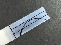
So here it is, the Robocam Plate Mod =)
View attachment 1
Indication:
3000W Cyclone middrive (I recommend not using your middrive until you've reinforced the mount so that all your parts will be perfectly straight)
Features:
-Light weight
-Rounded edges
-Proven to handle at least 6660 watts as tested by Gman (Thanks G!)
Parts List:
1/8" x 2" aluminum
Two 1/4-20 coupling nuts (mine were 0.8815" or 22.4 mm long)
1/4" washers
Two 1/4-20 x 2-1/2" screws
Two 1/4-20 x 3" screws
Two 3/8" x 1/2" x 1-1/2" steel spacers
Four 1/4" x 3/8" x 1" steel spacers (I chose 1" because that was all I could find, two 1-1/2" spacers would be ideal because they go inside the spacers above)
Blue threadlocker (this is what I use http://smile.amazon.com/Permatex-24240-Medium-Strength-Threadlocker/dp/B000AANXJ0?ie=UTF8&psc=1&redirect=true&ref_=od_aui_detailpages01)
Some Tools Needed:
Grinder with a metal cutoff disc (or any tool for cutting/shaping the aluminum)
Rotary tool with a metal cutting disc (for cutting the screws/bolts and steel spacers)
Instructions:
There are many ways to implement this idea. This is just how I did it.
Be sure to use blue threadlocker on all threads.
1. Find something the same diameter as the back of your Cyclone, or make a circle out of posterboard or cardboard. This circle will be used to trace the shape of the back of the Cyclone onto the aluminum. You can use a compass too.
2. Cut the aluminum
3. Put the plate onto the Cyclone and trace the locations of the stock motor bolts. This will help guide where to drill the holes. Use a ruler to help you mark the locations of the other bolts. The two bolts are not the same distance from the motor, so don't make the same mistake I did by measuring only one side. It might be a good idea to practice on a piece of cardboard.
4. Take the black spacers that came with the kit and make their holes big enough for the 1/4" screws/bolts. I used a tap, but you can drill them out as well.
5. Insert the smaller spacers into the larger spacers. Trim the smaller spacers until they're flush with the larger spacers.
]
6. Put it all together using blue threadlocker. Round the edges using a grinder (this will save your foot).
Here are a few parts that I purchased from Lowes.
Feel free to ask any questions!
gman1971 said:
...No prob man, you were the 1st person who implemented the side plate upgrade without buying an LR upgrade mount, and that what worked for you did work very well for me too, so thanks....


")