Active pre-charge/inrush control

izeman said:
Arlo1 said:
...there is a measurable ring across the second contactor as high as 830v even though its not on and there should be no current flowing anywhere. I am going to order a few 1200v rated igbts to try this with....
the voltages you're playing with frighten me. A LOT. REALLY deadly forces are present. i even handle my 80v system with great care ;)

Yes great care must be taken.

1 I use 2 contactors one on the top of the pack and 1 on the bottom and in time maybe 1 in the middle as well. In the middle of the pack right now I have and Anderson which I unplug any time I service anything or when the car is not in use as I am in the middle of the build at the moment.

But if you want to learn to build 1000+ hp you will never do it with 80v.....

This build I am aiming to break 300hp at the wheels and that would be very hard to do with lower voltages. As well would require the leaf motor to be rewound.
 
Hello,

i want to use this circuit with Arduino. Can someone show me where I have connect arduino pin? I want just supply HIGH from arduino and this circuit will slowly power my ESC.

Im using IRFB4110 mosfets.

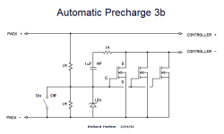
Automatic%20Precharge%203b-schematic.png

Thank you!
 
Here is what I have for Arduino code.

You will need to edit the math for the input (DO NOT EXCEED 5V!!!) My isolated amps only produce 1.2v at 0v and with my votage dvider they produce 3.0 at 490v and above.

I added undervolt and over volt lockouts as well. My Arduino turns on the whole cars systems where it is happy :)

Code:
/*

Precharging program for EV use.  I expect this program to be much bigger when the CRX works Arlin!!! :D


NEEDS TESTING

*/


// the setup routine runs once when you press reset:

//////////////////////////////////////////////////////////////////////////////////////////////////////////////////////////////

void setup() {


Serial.begin(9600); // initialize serial communication at 9600 bits per second:

pinMode(12, OUTPUT);//

digitalWrite(1, LOW);//Makes contactor outout LOW initially (zero)

int contactorstatus = 000;


}


// the loop routine runs over and over again forever:

//////////////////////////////////////////////////////////////////////////////////////////////////////////////////////////////

void loop() {

// read the input on analog pin 0:

  float Packvolt = (analogRead(A0)*1.5755)-381.3;//Outputs values from 0-1023, so 2.048 will make the maximum voltage 500V.  Set appropriate voltage divider!

  float Prechargevolt = (analogRead(A1)*1.5755)-381.3;//


  int contactorstatus =digitalRead(12);
  

  if  (Packvolt>340&&Packvolt<480&&Packvolt*0.965<=Prechargevolt)// 95% precharge, change 0.95 to whatever to get you want your precharge to be

{

  digitalWrite(12, HIGH); 


}

// fat print statement. should display stats over serial


  Serial.print("Pack voltage: ");

  Serial.print(Packvolt,4);

  Serial.print("  Precharge voltage: ");

  Serial.print(Prechargevolt,4);

  Serial.print("  Contactor status: ");

  Serial.print(contactorstatus);


  Serial.println();   //return to next line (/n)

  delay(200);        // delay in between reads for stability

  }
 
That might be tricky. The Audrino outputs are 5v. The 4110's want 12v. You could drive a small logic level FET with the Audrino to ground the gates on the main FETs (instead of a mechanical switch). You could possibly use a small relay also, but they draw a lot of current.
 
Hmm...

I'd suggest getting the right FET and test again. That one may be damaged.
Measuring the voltage between the gate and source will tell what's going on.
 
I have a hard time hearing, but it does seem to be working. If the switch is on when you make the connection to the ESC, it will spark just like a straight wire. That connection should be made before turning on the switch. When the ESC was sparked on, the sudden voltage change pumps charge through the bipolar cap to the gate (a good reason to use the zener diode). 20v on the gate is around the self-destruct level.

The only thing I didn't understand is why the gate voltage was dropping slowly, It should stay pegged at 12v.
 
fechter said:
The only thing I didn't understand is why the gate voltage was dropping slowly, It should stay pegged at 12v.

do you mean the sudden drop for a second? when i push the motor on hard?
 
BShady said:
do you mean the sudden drop for a second? when i push the motor on hard?

I guess that could explain it. I don't really make out the audio well (hearing impairment).
 
fechter said:
If the switch is on when you make the connection to the ESC, it will spark just like a straight wire. That connection should be made before turning on the switch.

if you connect the battery with the switch already in on position, shouldn't it not than still work as the automatic precharge?

like this version:

https://endless-sphere.com/forums/viewtopic.php?f=3&t=40142&start=125#p712738

I have built this 3a circuit (no switch can be used in this case so it needs to work automatically), but it doesn't seem to go smoothly.
It sparks like a straight wire.
The 1M resistor which was suggested to add between G and S i have not soldered to the circiut yet (me idiot have covered all parts with hot glue), but should't it at least do properly precharge if the Controller caps are fully discharged before? or could the gate still get a few volts "from the air" without the pull down resistor?
 
one dumb question.

the side with the black strip on the zener diode connects to the negative side or to the Gate? I just fried 2 mosfets and I was getting only .5v (half of a volt) on the gate. I have a feeling I put the zener backwards :roll:
 
fechter said:
If one wants to use this without a switch and just disconnect the battery, the schematic below should work.

there seems to be an issue with the 3a shematic. i have built it already twice and it did not help against sparking.
the 1M resistor across the zener which was suggested later i have not added yet, but what i have done is shortening the input and output to make sure everything is discharged (0,0..V) and the gate is down, but it doesn't change anything so i believe the addition of the resistor also would not help.

Does anyone have an idea where the problem lies?
I thought that it maybe could be that the gate charges too quick so that the FET already acts like a piece of copper at the same time when the conenction is made.

The version with the switch - which always worked like a charm - i can't, or better say i don't like to use since the sparking should be avoided when attaching a removeable downtube battery (it has 13s 48V).
All parts like recommended. The FETs i'm using are 3 pcs IRF3077.
 
teklektik said:
fechter said:
You could try using the switch to short the gate to source and leave the 1M resistor always on. When the switch is on (gates shorted) the output will be off but the 1M resistor will drain 1uA per volt on standby. This is a very small amount of drain and would be OK for years.
I like it.

I've taken the liberty to update the original draft as 3b to reflect the added 1M resistor and alternate switch connection per izeman/fechter recent efforts:

file.php

Switch is optional - omit for automatic-only operation.

Is this schematic the latest version? I am looking to build this circuit to switch on my 12S system (50.2V max) which pulls 70A max.

Thanks!
 
izeman said:
yes it is. i would suggest 2x 3077 bolt to the bike frame or another meaningful heat sink. they will get very hot.
to be safe, use 4x 3077, that will be easy on them.

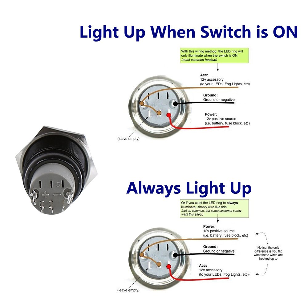
So in this version, the switch is open for ON, and closed for OFF. Do you know if it's possible to wire an ON/OFF switch like this (https://www.amazon.com/dp/B01D2S6LDQ) such that LED turns on when the switch is open?

61iEWZzfnBL._SL1000_.jpg


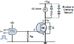
Alternatively, could you use Transistor-Transistor Logic to switch on the circuit, like so?
tran28.gif
http://www.electronics-tutorials.ws/transistor/tran_7.html
 

Attachments

  • Schematic.png
    Schematic.png
    5.8 KB · Views: 1,493
What's the advantage of the switch configuration in the Automatic Precharge 3b compared to this way? On-On toggle switch vs On-Off?


25ixa2x.jpg

Vedder switch: https://github.com/vedderb/SparkSwitch
 

Attachments

  • VedderSchematic.jpg
    VedderSchematic.jpg
    88.1 KB · Views: 1,494
Back
Top