tahustvedt
10 kW
Yeah the midnight sun is awesome. Too bad it's overcast. I hope for better weather soon, it's been pretty grey so far this summer.
")
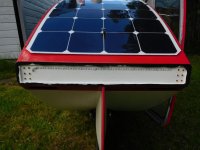
When you add them, Ihighly recommend doing it as either a separate light fixture at least a small distance from the regular taillight, or making it a segment htat is not normally lit at all, easily noticed vs the brightening of an existing segment.tahustvedt said:I don't have any brake lights, but maybe I should add some now that the panel is coming off. It's not required by law.
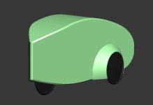
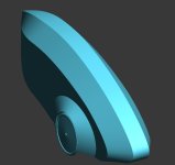
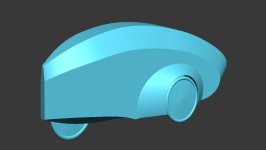
tahustvedt said:Thinking about making a new version.
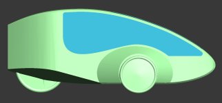
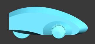
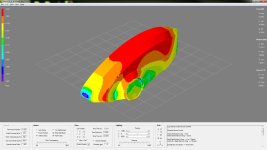
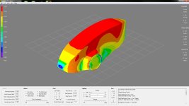
That is very interesting, what are the major factors to the so much higher drag of the first velo shape? Is it the area below the rear lights that causes too much underpressure? Is it the free standing wheels?tahustvedt said:The CFD run shows that this is a superb shape. A little over one fifth the drag of my first velomobile build. I will run the more blocky design tonight and will have the result tomorrow.
tahustvedt said:The exposed wheels create a hell of a lot of drag, and you're right about the rear. There's a low pressure area under the rear end of the old one, and the total is a strong downforce on the velomobile, which probably wastes a lot of energy. It produces a bit more downforce than drag. The new shape barely wastes any energy at all on downforce. 1,1 N on the new one as opposed to 78 N downforce on the old one at 40 km/h.