ULtra Compact 1800W charger + Eltek programming

Sorry to hear about the "rectifier" failure. That's a big loss. At least the one I have wasn't cheap, but I bought it new. There are some at better prices now.

I was involved with a number of safety systems (accelerator controls, X ray machines, etc), there are safety rated relays, and they tend to fail open if properly selected for the application. Regular solid state relays are generally not allowed in safety systems. They are SCR or FET based and they fail shorted. In most designs that doesn't fit the definition of a "fail safe component".

For a safety system generally two independent circuits and separate controls are required. Probably don't need to go quite that far here, but one could.

How did you determine the 3.3V was isolated? Do we have a schematic of the "rectifier" module?

This project will not be easy, is it worth the effort and risk? The Meanwell LED supplies are easier and very robust. Are you familiar with those? Their efficiency is high and they are adjustable in both CC and CV. The only thing you might want to add is end of charge disconnect.
 
Yep, i learned the hard way. Next time i post here the question before i do action.
I hope that only the PCB where i found the 3.3V is damaged and i can get a replacement from Eltek.

X ray is a interesting field especially X ray spectroscopy.
I have googled but not found a seller for 100% fail open relay. I only found a web-page with this info.

"One disadvantage of solid state relays is their tendency to fail “shorted” on their outputs, while electromechanical relay contacts tend to fail “open.” In either case, it is possible for a relay to fail in the other mode, but these are the most common failures. Because a “fail-open” state is generally considered safer than a “fail-closed” state, electromechanical relays are still favored over their solid-state counterparts in many applications."

On another web-page i have found information that relays switch about 100k+ times @ rated current and than they tend to fail.
But the solid-state ones about 50m+ times. If they are cooled right.

So i will risk my battery's life with the solid-state relay. I still find overall it the better option.

I have no schematic but measured no connection between the GND from the 3.3V system and the main DC out.

Had a MW RSP 48V before and it had stopped automatically @ 41.5V but about 6% less eff..

It seems that a very high voltage did came from the CAN right to the 3.3V PCB. I had seen and heard sparks fly.

Is cutting edge tech worth it ? Yep, every cent.

Merlin has still some 50pcs left https://endless-sphere.com/forums/viewtopic.php?f=31&t=83288&p=1222770&hilit=eltek

Enough for every try and error experiment. :)
 
That's a good price.

You might consider using both a SSR and a mechanical relay for redundancy, controlled by separate microprocessors. That's the kind of thing commonly done, though safety rated PLCs or straightforward safety logic were used instead of microprocessors. And the X rays we produced were used for many things including several types of spectroscopy. The strongest beams would have been fatal in microseconds, or melted through the aluminum vacuum chambers in a few seconds, so the safety systems were layered and very fast acting.

So burning down the house isn't quite at the same level of risk, but still an important concern.

Since the relay we're talking about only has to actuate once per charge cycle a hundred thousand cycles should be adequate for most any application. You can change them proactively if you are concerned.

If you consult any large electronics supplier they should have "safety rated relays", the ones we used were from Potter and Brumfield as I recall. But any quality relay operated well within its specifications will likely be adequate (not at full rated current), especially if two are used in truly redundant configurations. The SSR's fail from voltage spikes which can occur at any time, wearout is not the issue. The same voltage spike will not harm a mechanical relay.

If you could shift your battery voltage into the range of the Eaton supply the project would be much easier. If your pack was 11, 12, 13 or even 14S it would be in the rated range of the supply to adjust the voltage, depending on the cell ending voltage you are aiming for. 12, 13 and 14S packs are common, just use one of those and set the APR48-3G to suit.

Good luck on your project, and be safe.
 
Thanks for the detailed insights. :shock:

Ah yeah i remember switching high currents create high Voltage spikes. Also rare sun erruptions.
A better option might be 150V FETS on the DC line. Should be sturdier.

Burning down anything with my battery is very unlikely. I use 18650 li-ion and i would set default Voltage to 43.5 this would if everything fails only lead to a overcharged battery which would steal my battery some 50-100 cycles. But it would still be funktional.

I still want know if 0A or disable CAN command is possible before i think of the additionaly costs for relay. It would be less complex and fail safer.

Actually i use 20S split only to charge 10S. my controller is limited to 20S.
 
So can someone tell me/us what options are safe to power the Arduino with the CAN module ?

Or better if someone could find a way to make the 3.3V safely use-able ?

Thanks.
 
More progress.

Here pictures from opened Flatpack2 HE. It have seen no "If removed warranty void" stickers! :)

This is the PCB where a 3.3V and 3V source is. I can see 3 IC's which look like V. regulators. On left the GND. I am not 100% sure if its isolated. I'm not a EE!
http://imidacloprid.bplaced.net/Flatpack2HE1.jpg
The Arduino 8Mhz 3.3V + the MCP2515 module consume while running about 14 mA this should be in the safety margin and not the cause of the problems i had. Except if it was a 3.3V reference.

This PCB is sadly soldered with many pins. The fans 12V might also be use-able but i will not try it again. :)
http://imidacloprid.bplaced.net/Flatpack2HE2.jpg

Quality!
http://imidacloprid.bplaced.net/Flatpack2HE3.jpg

This film capacitor is easily lift able. The pins under it hard to cut/desolder.
http://imidacloprid.bplaced.net/Flatpack2HE4.jpg

After both female screw are loosen the pins need to be cut/desoldered than the black terminal can be removed and cables can be soldered instead. making it a lot more robust against loosening connectors.
http://imidacloprid.bplaced.net/Flatpack2HE5.jpg

Happy tinkering... :wink:

Oh, i sell my failed FP2HE I'm open to offers. PM me. Its also now a little more damaged. :D
 
imidacloprid said:
So can someone tell me/us what options are safe to power the Arduino with the CAN module ?

Or better if someone could find a way to make the 3.3V safely use-able ?

Thanks.
feed either the AC input or the DC output to a tiny isolated power supply.. then run it off that.
 
Hi All !

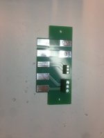
I have done a small breakout board for the Flatpack2 and Flatpack2HE.

It looks like this


Flatpack_board.jpg


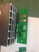
And inserted in the Flatpack it is like this:

Flatpack_board_2.jpg

REgards
/Per
 
Hi All !

I have dived into this pool of frustration.
Been tinkering all week with a FP2HE and various things to communicate with it.

1st setup:
FP2HE + Eltek Smartpack + Eltek Power suite on PC + Kvaser Semipro USB-CAN adapter.
I could set all kinds of things in the FP2 but not the default voltage or current.
I did not do any logs from that session because I wanted to be able to set the default voltage.

2nd setup:
FP2HE + Kvaser Semipro USB-CAN adapter.
I was able to set the defaul Voltage using the Kvaser software CAN King.
But I did not find it to be that consistent, it worked sometimes and sometimes not.

3rd setup:
FP2HE + Duinomite Mega MMBasic 4.5 with CAN lib
I was able to read packages from the FP2 but when I tried to send anything to it the Duinomite complained about the message type.
I don't know why but it was really annoying, I had spent a couple of hours in creating a program on a board that is pretty interesing,
but it seems the CAN library is fault when trying to send EID frames....... Haven't had the time to look at the code for the CAN lib
to see if it is fixable.

4th setup:
FP2HE + IXXAT USB-to-CAN V2 compact + Ixxat canAnalsyer3 mini
I was able to read packages from the FP2 and also to set the default Voltage.
And this time with consistancy, It works every time now.

Logging in as described earlier in the thread and then:
With this ID: 0x05019C00 and data: 0x29 0x15 0x00 0xLL 0xMM

When I send that frame I get this back:
id: 0x05019C00 and data: 0x2B 0x15 0x00 0xLL 0xMM


Does anyone know what the different parts of the data actually means? Apatr from the voltage ?
Is the second data byte a variable number representing the Default voltage or is that the first data byte?

BTW i have ordered a Leonardo CAN also ....

Best Regards
/Per
 
How did I miss this awesome thread??
So the Flatpack 2 HE can be connected in series, with no modification?
Is there a practical limit where really bad things may start to happen? 5s? 10s?
 
Hi !

@that1Guy: Yes termination on both ends is good practice. 120ohms on each end, giving a 60ohm resulting resistance between CANhigh and CAN low.

@okashira: I know people in sweden using atleast 4 in series of the old version that is silver(also called Flatpack2 but not the black High efficiancy verision)
So over 200 volts atleast. I have been thinking about using 8 in series for Nissan leaf Charging......

REgards
/Per
 
Be aware that the CAN Hi and Lo are not isolated so don't just wire the CAN connections directly when running in series otherwise you'll be sending 48V+ through the CAN wires.
 
HI !

@dgh853: Yes I read that in this thread, so I'm staying away. But If the PSUs are connected in series It would only need one to thottle the current right.
So that way one can have a leonardo for example conencted to only one of the PSUs in a stack.

Regards
/Per
 
If users are happy to make the permanent settings such as default voltage and walk-in for each rectifier before wiring them in series all good.

There are other messages people may want to use than just current control so even if you're right about one rectifier controlling the flow in series some people may still want to connect multiple rectifiers via CAN.

Using an Arduino board with an isolated CANBUS can circumvent the problem.
 
Hi circuit !

That is a really nice board and package.

I just found that one today while browsing through your BMS products.
Does the BMS board control the Flatpack over serial ?

Do you care to exchange info on the protocol ?

I haven't come that far yet but I'm getting further every day.

Regards
/Per
 
Yes, BMS controls the flatpack. Now on final stages of firmware.
The UART-CAN converter is a nice project on it's own, completely isolated, powered only from one side, also sub-100μA power consumption in standby mode (while still listening to CAN bus). So it can be used as a generic converter, not just for Eltek.
The protocol is based on information that we got from Eltek. Basically, from what developer told me, it is not that far from what is published on this thread.
 
Sounds Awesome!!!!

Lookning good !

Ok I guess I have to continue digging in the CAN swamp of the Eltek then......

Drop me a PM if you change your mind.
I have access to FlatPack Solar units for testing if that can be of interest! :)

Thinking of getting me some of those Rectiverters also.

Have you tested the Chameleon, Full IP65.......

Regards
/Per
 
Still thinking thinking about current control with multiple flatpacks in series. It's a good question. Not sure if it would work... Ideally all flatpacks are programmed for the current limit.
 
Let's say you have 10 flatpacks in series programmed for 50v 30A
So, the whole string will go to 500V 30A.

If you limit one to 5A. Once that ONE flat pack sees 50V it will try to taper current. Only one, though.

Let's say battery is at 300V. All flat packs will provide 50V and 30A max except the one programmed for 5A. Just 6 flat packs can provide 300V and 30A.
Each supply will push 30A until it's individual 30A limit is reached, until 300V.

Once 300V and 30A is reached, that one "5A" flat pack will reach its current limit. But there are 9 other flatpacks setup for 30A and 50V. The other nine, ignoring the current limited one, can do 450V and 30A. So even if the limited power supply went to 0v, the other nine would force current through it.
So 6 PSU can do 300V 30A. The other 4 must have 30A going thru them per Kirchoff's current law. So... This supplys may end up with a negative voltage!

Thus, current limit must be applied to all PSU in series or bad things will happen!

Voltage limit can be applied so only some PSU to achieve desired limit ( ie 50+50+50+30 = 180)

Conclusion, current must be applied to all psu in series. On the other hand, voltage limit can be defined by all psu in series added.
B careful with this though. All it takes is for one PSU out of 10 to malfunction and produce higher then 50v and damage your battery without a BMS.

Total summary, use a well designed BMS! Lol.
 
good point. there needs to be resistance in the loop so the CCCV logic can actually control. The battery has resistance.

If it is set up as badly as in your example, the one with the low current limit that gets negative voltage will blow. Maybe this could be prevented with diodes to clamp the voltage to zero at the PSU output, in case of reverse polarity

yet in practice i did not have such a failure
 
You can't go below certain level, like 30V or so (can't remember exact value). Below that, it will not work as expected, or will simply switch off.
This is why load sharing must be implemented. That can be done by coordinating voltages of all chargers, making sure one of then can work in CC mode in acceptable voltage range (in case of series connection).
 
Yes it sounds like it could get nasty if one tries that without current control on all the PSUs.


okashira said:
Let's say you have 10 flatpacks in series programmed for 50v 30A
So, the whole string will go to 500V 30A.

If you limit one to 5A. Once that ONE flat pack sees 50V it will try to taper current. Only one, though.

Let's say battery is at 300V. All flat packs will provide 50V and 30A max except the one programmed for 5A. Just 6 flat packs can provide 300V and 30A.
Each supply will push 30A until it's individual 30A limit is reached, until 300V.

Once 300V and 30A is reached, that one "5A" flat pack will reach its current limit. But there are 9 other flatpacks setup for 30A and 50V. The other nine, ignoring the current limited one, can do 450V and 30A. So even if the limited power supply went to 0v, the other nine would force current through it.
So 6 PSU can do 300V 30A. The other 4 must have 30A going thru them per Kirchoff's current law. So... This supplys may end up with a negative voltage!

Thus, current limit must be applied to all PSU in series or bad things will happen!

Voltage limit can be applied so only some PSU to achieve desired limit ( ie 50+50+50+30 = 180)

Conclusion, current must be applied to all psu in series. On the other hand, voltage limit can be defined by all psu in series added.
B careful with this though. All it takes is for one PSU out of 10 to malfunction and produce higher then 50v and damage your battery without a BMS.

Total summary, use a well designed BMS! Lol.
 
man id love to get my hands on a flatpack s 48 1800.
i have got quotes from alibaba , lowest was 340 usd/peice ex shipping. still too crazy.
 
Back
Top