In the 10 last years i have built dozens of battery packs ofvarious engineering level.
For all those i have kept the same common rules:
1: Good current sharing across every cells,
2: good thermal management
3: good mechanical resistance against vibration and moisture
For the point 1, this is one very important that most people pay attention to, however some very stupid errors can ruin the pack very easy.
For exemple, for my mongoose 2.3kWh buld in 2008, i have used parallel connections that connect in serie to each other by connecting them to both end of each row.. but did not used serie connections in the middle and thre is a perticular reason for that: the current is function of the cell internal resistance, and internal resistance is function of cell temperature. The cell temp at the end of each paralle row is lower than the temp in the middle. Think about it, this is very simple! if the Ri of the cell in the middle is lower due to higher temp, it will conduct MORE current and cell that are at both end will be colder and conduct less current... The serie connections made closer to these colder cell actually compensate and make the total curent share over the entire paralleled cells to be uniform. This pack ran over 16500km and only required few rebalancing and it does not have any BMS.
So YES current share and thermal management ARE IMPORTANT :wink: and if well made the pack last longer.
The second point: the thermal management is also very important. as well for mechanical tolerance and cell health... Hot glue is the cheap chineese PROBLEM.. I have dissassembled hunderd of OEM ebike battery that all had problem with bad cell connection due to vibrations due to hot glue that just unstick from the cell... Hot glue is bad for lower temp it become harder and break. Then the cell only rely on the cell connection to mechanically stay in place witch is bad.
Point 3: Good Mechanical resistance. i have dissassembled thousand of Makita packs.. yes thousand!

and i also say the improovement made over the various version and years.
I can conclude that the packs that have the most problem are due to: Bad cell (bad apple), and bad cell connections due to hard environment where they are used at. and cells had completly broken spoweld... over teh years Makita have reduced the thickness of the nickel sheet and extanded the surface to allow flexion to take vibrations.. but these cells are now also very nicely hold together by plastic structure witch take most of the mecanical vibrations.
DIY Pack fail due to short circuit between cell case because people think the thinny green skin is strong enough to isolate between cells. ERROR!.. cell wirring is also something to think about... the place where the wires path is is also VERY critical.. that wiring must be secured correctly for any temperature and not rub against other sharp electrical connections... the weight of the pack must not be supported by balance connections wires too... all fact that seem an evidence for some is often completly forgot by others...
This IMPORTANT thread will get alot pages over the month i feel! 8)
Doc

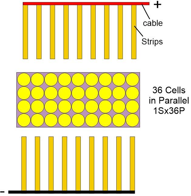
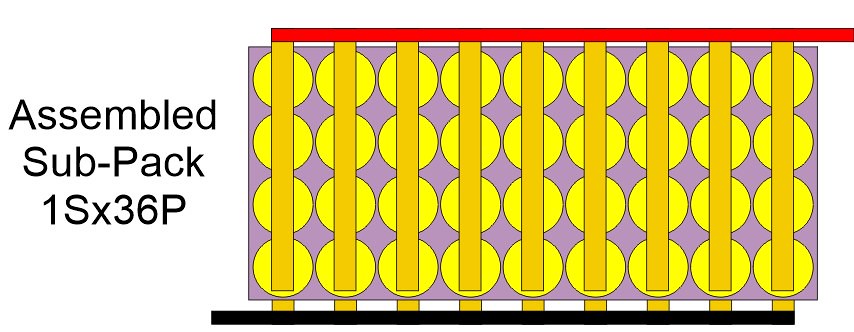
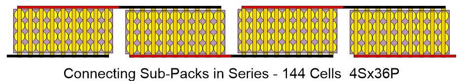
") YES it is one of the best DIY design because it provides large cross section and you only need to cut one nickel strip which you can use for series and parallel connection at once (instead of cutting many small ones). Thats why you may like it that much.
YES it is one of the best DIY design because it provides large cross section and you only need to cut one nickel strip which you can use for series and parallel connection at once (instead of cutting many small ones). Thats why you may like it that much.