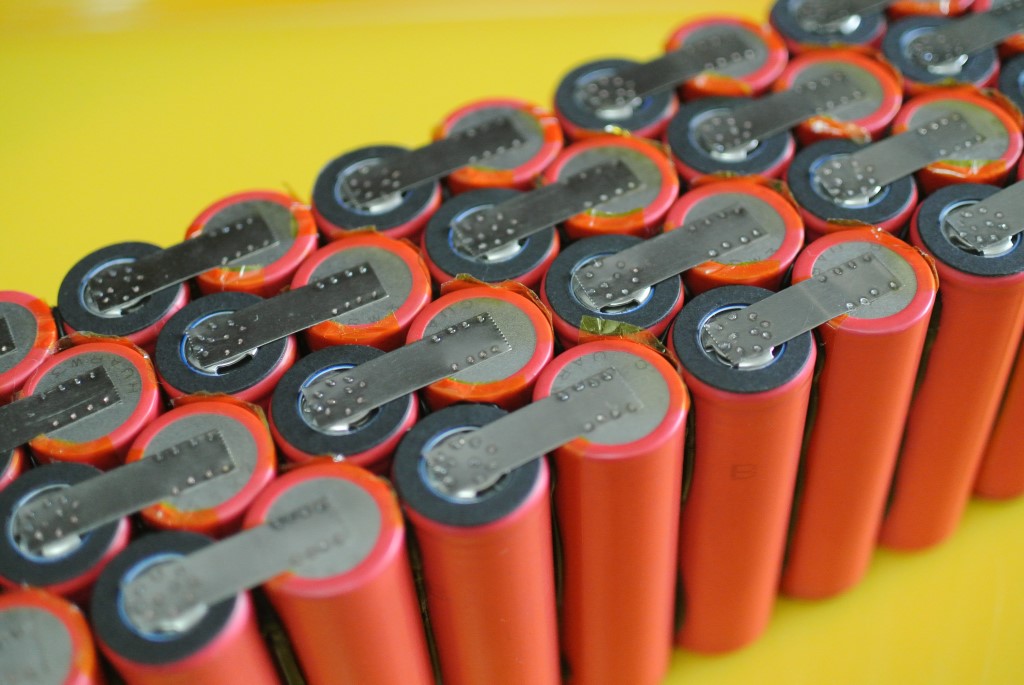
Common pack design mistakes, how to avoid?

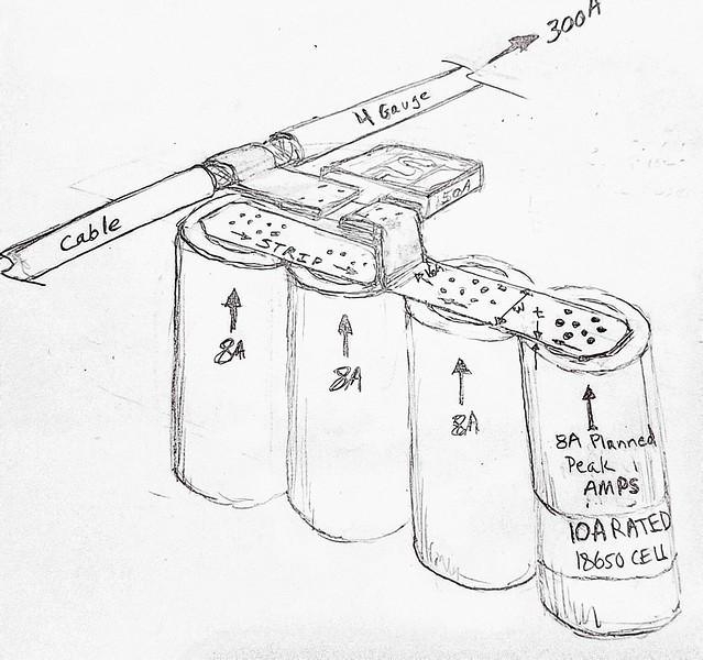
Below is an idea for cell-to-strip-to-fuse-to-cable connection. The cells are rated to 10A peak discharge. My peak load will pull about 8A. The cells feed into the nickel strip of some thickness t and width w. The nickel strip then sandwiches a blade from a 50A blade-type low voltage fuse. A similar connection is on the other blade. Nickel strip is then wrapped around the cable and soldered. Insulation is placed between the fuse and battery terminal. This is all pressed flat for low pack depth. The back side is a similar connection except no fuse.

30154147384_2ba88cfd66_z.jpg


Here is a link fuses that are about $0.70/ea. http://www.ebay.com/itm/New-10pc-MA...e-Auto-Boat-Truck-RV-50A-50-AMP-/121875028161

I haven't worked with nickel sheet. Hoping it does not fracture when folded.

mkp
 
mistercrash said:
How much current can be carried by that strip of material joining the groups of four cells?

From a rough calc, 10mm x 0.2mm nickel strip will have a voltage drop of about 1.5% for 16A and 5 inches of length. I am having a hard time sourcing this size strip without it being plated steel? Any thoughts on Ni plated steel vs all-nickel strips? Steel is 2.4x more resistant than Ni and Ni is 4x more resistant than Cu. More resistance = larger voltage drop = lost energy to heat. Also, I don't like the idea of plating as it could fail :!: .


eTrike said:
...You might consider using a fuse holder instead of spot welding the strips....

Thanks eTrike. It is hard to find fuse a holder that doesn't add significant bulk to the sub-pack. I like the idea of spot welding and soldering to the blades for a more permanent connection.

I am concerned about the labor involved in fabricating all the strip/fuse sub-assemblies. But at least they are all the same and repeated 100's of times. So there's that. :|
 
I would avoid plated steel. Too much resistance means lots of loss in heat and big voltage sag. The steel could turn red hot and melt at too high currents.
We have an example of the possible complications here : https://endless-sphere.com/forums/viewtopic.php?f=14&t=83505&start=50#p1234386

For pure Nickel strips see my post here : https://endless-sphere.com/forums/viewtopic.php?f=14&t=57810&start=175#p1214787

But in summary

Let's say your strips are 10 mm width by 0.2 mm thickness
It means your strips have a cross sectionnal area of 0.000002 m2

Now let's say you want to use 10 cm long strips... you can calculate the resistance of each strip...
Now let's compare it for different metals, using resistivity tables from here : https://en.wikipedia.org/wiki/Electrical_resistivity_and_conductivity

1. COPPER STRIPS (10mm width x 0.2mm thick x 10 cm lenght)
Resitivity of Copper is 1.68 x 10^-8 Ohm.m
So the resistance of a 10 cm lenght is : [1.68×10⁻⁸ Ohms.m] x [0.1m] / [0.000002 m2] = 0.00088 Ohms or 0.88 milliOhms
Since dP (heat loss) = R x I^2,
At 5 amps, 0.02 W of heat will be generated by just one 10 cm strip.
At 10 amps, 0.09 W of heat will be generated by just one 10 cm strip.
At 20 amps, 0.35 W of heat will be generated by just one 10 cm strip.
At 30 amps, 0.79 W of heat will be generated by just one 10 cm strip.

At 40 amps, 1.41 W of heat will be generated by just one 10 cm strip.
At 50 amps, 2.20 W of heat will be generated by just one 10 cm strip.
At 100 amps, 8.80 W of heat will be generated by just one 10 cm strip.
If I assume that a 1W CONSTANT heat loss PER STRIP is the max loss I can tolerate, I could go for up to 33.7 amps (SUSTAINED) with Copper of those dimension specs.
If I assume that a 5W PEAK heat loss PER STRIP is the max I can tolarate, I could go for up to 75.4 amps (PEAK) with Copper of those dimension specs.

2. NICKEL STRIPS (10mm width x 0.2mm thick x 10 cm lenght)
Resitivity of Nickel is 6.99 x 10^-8 Ohm.m
So the resistance of a 10 cm lenght is : [6.99×10⁻⁸ Ohms.m] x [0.1m] / [0.000002 m2] = 0.00349 Ohms or 3.49 milliOhms
--> 4 times more resistance than pure copper = 4 times more heat power loss than with copper (dP = R x I^2)
Since dP (heat loss) = R x I^2,
At 5 amps, 0.09 W of heat will be generated by just one 10 cm strip.
At 10 amps, 0.35 W of heat will be generated by just one 10 cm strip.
At 20 amps, 1.40 W of heat will be generated by just one 10 cm strip.
At 30 amps, 3.14 W of heat will be generated by just one 10 cm strip.
At 40 amps, 5.58 W of heat will be generated by just one 10 cm strip.
At 50 amps, 8.72 W of heat will be generated by just one 10 cm strip.
At 100 amps, 34.9 W of heat will be generated by just one 10 cm strip.
If I assume that a 1W CONSTANT heat loss PER STRIP is the max loss I can tolerate, I could go for up to 16.9 amps (SUSTAINED) with Nickel of those dimension specs.
If I assume that a 5W PEAK heat loss PER STRIP is the max I can tolarate, I could go for up to 37.8 amps (PEAK) with Nickel of those dimension specs (0.2 mm thick, 10 mm wide !)

3. CARBON-STEEL STRIPS (10mm width x 0.2mm thick x 10 cm lenght)
Resitivity of Carbon-Steel is 1.43 x 10^-7 Ohm.m
So the resistance of a 10 cm lenght is : [1.43×10⁻⁷ Ohms.m] x [0.1m] / [0.000002 m2] = 0.00715 Ohms or 7.15 milliOhms
--> 8 times more resistance than pure copper = 8 times more heat power loss than with copper (dP = R x I^2)
Since dP (heat loss) = R x I^2,
At 5 amps, 0.18 W of heat will be generated by just one 10 cm strip.
At 10 amps, 0.72 W of heat will be generated by just one 10 cm strip.
At 20 amps, 2.86 W of heat will be generated by just one 10 cm strip.
At 30 amps, 6.43 W of heat will be generated by just one 10 cm strip.
At 40 amps, 11.4 W of heat will be generated by just one 10 cm strip.
At 50 amps, 17.9 W of heat will be generated by just one 10 cm strip.
At 100 amps, 71.5 W of heat will be generated by just one 10 cm strip.
If I assume that a 1W CONSTANT heat loss PER STRIP is the max loss I can tolerate, I could go for up to 11.8 amps (SUSTAINED) with Carbon-Steel of those dimension specs.
If I assume that a 5W PEAK heat loss PER STRIP is the max I can tolarate, I could go for up to 26.4 amps (PEAK) with Carbon-Steel of those dimension specs.


4 . STAINLESS-STEEL STRIPS (10mm width x 0.2mm thick x 10 cm lenght)
Resitivity of Stainless-Steel is 6.90 x 10^-7 Ohm.m
So the resistance of a 10 cm lenght is : [6.90×10⁻⁷ Ohms.m] x [0.1m] / [0.000002 m2] = 0.0345 Ohms or 34.5 milliOhms
Since dP (heat loss) = R x I^2,
At 5 amps, 0.86 W of heat will be generated by just one 10 cm strip.
At 10 amps, 3.45 W of heat will be generated by just one 10 cm strip.
At 20 amps, 13.8 W of heat will be generated by just one 10 cm strip.
At 30 amps, 31.1 W of heat will be generated by just one 10 cm strip.
At 40 amps, 55.2 W of heat will be generated by just one 10 cm strip.
At 50 amps, 86.2 W of heat will be generated by just one 10 cm strip.
At 100 amps, 345 W of heat will be generated by just one 10 cm strip (IT WILL MELT FOR SURE !!!)
If I assume that a 1W CONSTANT heat loss PER STRIP is the max loss I can tolerate, I could go for up to 5.4 amps (SUSTAINED) with Stainless-Steel of those dimension specs.
If I assume that a 10W PEAK heat loss PER STRIP is the max I can tolarate, I could go for up to 17.0 amps (PEAK) with Stainless-Steel of those dimension specs.

So of course, nickel plated steel in not the same as bare steel.... You could make calculation accounting for the plating thickness to calculate the nickel cross sectionnal area to add to the steel core surface area.... But keep in mind plating is usually very very thin, somewhere between 5 and 50 microns of thickness... So the nickel plating is kind of non significant...

I would definitly avoid nickel plated steel.
Heck I'm even trying to stay away from bare nickel.
I'd rather go for nickel plated copper. See my post here : https://endless-sphere.com/forums/viewtopic.php?f=14&t=60364&start=25#p1235640
Why ? Copper is a great conductor... But over time it oxidizes.... So resistance increase in contact points. Solution ?
Nickel really does not oxidises that much, but is a bit less conductive..
So Nickel-plated Copper core is the best of both worlds in my opinion.

Just my two-cents
 
Just as a side note... You might have noticed from the Wikipedia's resistivity table that Gold is not as good a conductor as Copper.
Why do we use it in Hi-Fidelity stereo equipement then ???
Why are most high quality Hi-Fi cable terminals/connectors Gold-plated ?

We know that Nickel oxidises a lot less than Copper ; almost no significant oxidation.
But if you heat up Copper past certain temperatures, I oxides crazy fast in contact with the oxygen from the air. And that resulting layer of copper-oxide is not good at conducting electricity.

Gold, on the other hand, does not oxidise at all (it's a very noble metal), so gold-plated connectors make for very reliable connection in Hi-Fi equipement.
The thing is gold is way too expensive. So the Nickel-plating of Copper is good enough for my own purpose... Gold plated Silver would probably be great !
Trust me, if I could use supraconductors, I would !

After all, the battery is THE single most important part of an eBike in my opinion.
 
Re the drawing... I'm not sure I'm understanding it. Does the negative of the next group that isn't shown hook to that wire? And if so then why is it going off two directions like the start of a paralleling setup?
And if there is a fuse on the series connect, wouldn't it kill the whole series string when it went? I thought part of the benefit of putting up with the multiple connections of an 18650 pack was if one or two in a parallel group gets weak the whole series doesn't suffer as much because of the redundancy?

Also, how is the current sharing going to be with the 4p groups? Are the two center cells going to be seeing more current?

Not to badger you with questions, they;re just popping to mind right now... the last one was what kind of a system only sees 8 amp peaks. It would seem like even a low power set up would see more than that in bursts?
 
Voltron said:
Re the drawing... I'm not sure I'm understanding it. Does the negative of the next group that isn't shown hook to that wire? And if so then why is it going off two directions like the start of a paralleling setup? ....... It would seem like even a low power set up would see more than that in bursts?
'

The drawing shows a sub-group within the "sub-pack" illustrated near the bottom of page 2.

https://endless-sphere.com/forums/viewtopic.php?f=14&t=84412&start=25#p1237927

The sub-pack is 1Sx36P. There is 9 rows of 4 cells. The drawing just shows only one of those rows. So the total "planned" peak current capability is 8A x 36 = 288A which is why the 300A is shown in the 4 gauge cable.

The reason to do it this way is because of space constraints. I have to fit 11 of the sub-packs in series in a triangular shape. There will actually be two stacks of these for a total of 22Sx36P (792cells). 90V and 288A will certainly move some things. and that is only 1/6th of the overall total.

So, the benefit of doing it this way is the cell-to-cell connections are all parallel and the sub-pack-to-sub-pack are all series. The current draw on each cell is very uniform I think.
 
Matador said:
I would avoid plated steel. Too much resistance means lots of loss in heat and big voltage sag....

...I'd rather go for nickel plated copper.......So Nickel-plated Copper core is the best of both worlds in my opinion.

Thanks Matador. That was my thought too. I did find a rather inexpensive source for 0.2mm Nickel foil.

https://www.aliexpress.com/item/99-...mm-width-200mm-length-1500mm/32475681711.html

I think shearing to the width needed (10mm, 12mm, etc.) is the way to go. I think a paper cutter would do the trick.

I like the idea of Ni plated copper foil. I used to work for a composites company and we made plated waveguides. Adding a Ni strike over copper was common. But that was fresh copper in a bath-to-bath process. If you take copper foil, I think you would need to do an acid etch first to remove any corrosion to make sure the Ni remains adhered to the copper.

I'm actually a little surprised that Ni plated copper foil isn't readily available and Ni plated steel is. Cost of Cu vs Ni foil is about 1/20th (ref. McMaster-Carr) so Ni plated copper would likely be less than Ni foil. There is a good plating facility near my shop. Maybe I'll bring a couple copper sheets over to them to see what they can do.

Is 0.25mm copper foil difficult to spot weld using the lower cost spot welders?
 
mkp007 said:
Thanks Matador. That was my thought too. I did find a rather inexpensive source for 0.2mm Nickel foil.
https://www.aliexpress.com/item/99-...mm-width-200mm-length-1500mm/32475681711.html
I think shearing to the width needed (10mm, 12mm, etc.) is the way to go. I think a paper cutter would do the trick.

Nickel foil is a good idea...

But wow ! 138.88 USD (and there's the shipping fees too) is actually kind of expensive in my opinion, isn't it ?
I mean 0.2 mm (thick) x 200 mm (width) x 1500 mm (long) is actually 60 cubic-centimeter in volume... That's 60 mL volume of metal... Nickel has a density of 8.908 g/mL, meaning that the 60 mL translate to 534.5 grams of Nickel.
So at 138.88 USD/534.5 grams of Nickel, you pay 0.26 USD per gram of Nickel.
In Canada, Nickel coins made between 1955 and 1981 where 99.9% pure nickel... They cost only 5 cents and are 4.54 grams weight (https://en.wikipedia.org/wiki/Nickel_(Canadian_coin)), Now thats just 0.01 $ per gram (and CAD is worth less than USD).
So more than 26 times what it's worth in raw material. I understand you pay premium for the sheet shape formation of the material.... But personally I'd prefer copper sheets for less money AND better conductivity.

mkp007 said:
I like the idea of Ni plated copper foil. I used to work for a composites company and we made plated waveguides. Adding a Ni strike over copper was common. But that was fresh copper in a bath-to-bath process. If you take copper foil, I think you would need to do an acid etch first to remove any corrosion to make sure the Ni remains adhered to the copper.

I'm actually a little surprised that Ni plated copper foil isn't readily available
and Ni plated steel is. Cost of Cu vs Ni foil is about 1/20th (ref. McMaster-Carr) so Ni plated copper would likely be less than Ni foil. There is a good plating facility near my shop. Maybe I'll bring a couple copper sheets over to them to see what they can do.

I'm also very surprised that they don't sell Nickel-plated Copper... I have good hopes that it will become available on the market once people realise that that's what we really need for our batteries. Once people become sensibilized to this resistance issue, they won't be satisfied with bare nickel (strips or sheets). They will require Nickel-plated Copper as a gold-standard of quality. Then as the demand grows, the offer will follow... And the Nickel-Plated COPPER sheets or strips will become widely and readily available to the wide market.

You're right about the Acid Etch... I managed to Nickel-Plate Copper on small scale with good results, just using 99.9% made Nickel-coins (see here for photos : https://endless-sphere.com/forums/viewtopic.php?f=14&t=60364&start=25#p1235640). I didn't have any strong acid like hydrochloric acid to do the etch (so I sanded smooth my copper pieces with different grits up to 2000 grit wet sanding before plating).


mkp007 said:
Is 0.25mm copper foil difficult to spot weld using the lower cost spot welders?

I have no clue... I have no experience with spot welding.... My battery build prototype is solderless... (se here : https://endless-sphere.com/forums/viewtopic.php?f=14&t=57810&start=150#p1213147)
But I'd love to know if somebody on this forum has experience with Copper spot-welding.

I'm currently playing with and planning to rewire a MOT (Microwave oven-transformer)... Maybe I'll turn it into a spot-welder :mrgreen:
But for now I just pulled out the old secondary (2350 Volts AC) and repainted the ferrous core in black... Looks cool :
 

Attachments

  • IMG_0541[1].JPG
    IMG_0541[1].JPG
    92.5 KB · Views: 5,461
Found this video on copper tab spot-welding :
https://www.youtube.com/watch?v=jcXInB3YMBA
https://www.youtube.com/watch?v=NaqqfzFaM7w
0.007" copper thickness is equivalent to 0.18 mm thickness...
Not bad !

The welder seem kinda different than the cheap chinese spot welders though.
 
I just googled a bit "why copper is difficult to spot weld"...(look here : http://cr4.globalspec.com/thread/7404/copper-to-copper-spot-welding)

I mean of course people thought of Copper instead of Nickel waaay long before me. I doesn't take a PhD to figure out that Copper is 4 times more conductive than pure Nickel.
But people seem not to use copper much on this forum. Nickel seems more user-friendly than Copper... Why ???
That made me suspect that copper was not soo easy to spotweld, hence, people chose the next best thing : Nickel...

Seem like since copper has such a low resistance (which we want !), it make it harder to spot-weld.
Why ? To produce a good weld, you have to have a certain quantity of power dissipation in the form of heat.
But since copper has such a low resistance, you need to have more current to make the weld, or more voltage. (P = R x I^2... or P = V x I)

I'm crazy enough that I would want to weld 2 mm thick bussbars to my 18650s. I might as well find an alternative to spot-welding.
Copper is cheap... I bought 50 feets of 1/4 inch outer diameter copper pipe that I flattened. It cost me 40$ CAD. It gave me bussbars of around 10 mm width per 1.8 mm thick once flattened (I calculated a cross sectional area of 17.6 mm2, equivalent to 5 AWG gauge !)

Anyways, I'm pretty sure there are ways to spot-weld copper as we can see on the youtube video previously posted.
 
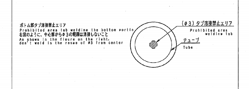
One point which seems to have been forgotten is the rule of Keeping welds clear of the center of the -ve base of the can.
Some of the manufacturers data sheets are very clear on this and even give dimentions of where not to put the welds to avoid sensitive internal areas.
This has been repeated on these forums previously.

[moderator edit to pics which provides an example of the point made here]

omW8OUx.png


PackBuild29.JPG
 
Welding 2mm on to the cells do require som special equipment.

Here is a 0,3mm nickel compared to the negative cap och a 18650 cell. click on the link and you also will see why you should not spot weld in the middle of the can, just like Hillhater stated
https://endless-sphere.com/forums/viewtopic.php?f=14&t=57291&start=425#p1011357
file.php
 
Hillhater said:
One point which seems to have been forgotten is the rule of Keeping welds clear of the center of the -ve base of the can.
Some of the manufacturers data sheets are very clear on this and even give dimentions of where not to put the welds to avoid sensitive internal areas.
This has been repeated on these forums previously.


omW8OUx.png


DFJ8MPH.jpg


so i try to weld at the outside edges of the nickel
 
I 'peeked' inside my Luna Cycle Shark battery pack. It was suggested that I link the pictures to this thread so ...
file.php

file.php

file.php

The full thread is here https://endless-sphere.com/forums/viewtopic.php?f=3&t=83817&p=1239761&e=1239761
 
LewTwo said:
I 'peeked' inside my Luna Cycle Shark battery pack. It was suggested that I link the pictures to this thread so ...
file.php

The full thread is here https://endless-sphere.com/forums/viewtopic.php?f=3&t=83817&p=1239761&e=1239761

Are those copper strips? I take it that is corrosion. Is that + terminal protection absorbing moisture? Maybe water is collecting at the bottom of your container?
 
Nice battery! I'm excited about the wave of cased batteries coming with plastic mount separators. Also watch for the innovations coming from EM3ev. We can still get the budget hot glued Batts for low prices, but I predict these better built batteries, while more expensive, will have longer service lives. AND DO come with better warranties.
 
mkp007 said:
Are those copper strips? I take it that is corrosion. Is that + terminal protection absorbing moisture? Maybe water is collecting at the bottom of your container?
They appear to be nickle. No that is a solder spot. I believe they may have tinned that spot for the balance lead but wound up soldering it further to the left.
 
When it comes to electrical conductivity, aluminum and zinc are both similar or better than nickel, and also much cheaper than nickel. I am persuaded that using 0.20mm thick nickel strips to form the paralleled sub-groups is reasonable, but for the thicker high-current series bus-bars, it seems to me that copper is easy and cheap to use there, but I'm told bare copper experiences corrosion (perhaps worse near the salt air of the beaches, but even in the desert, shiney copper turns brown with oxidation)

How about series bus bars made from thick copper and thinly plated by aluminum or zinc?

Micah Toll is selling a battery pack custom build-kit where he supplies the paralleled sub-groups with nickel strips and spot welds. The home pack-builder solders the series connections, with no fear of heat damage to the individual cells...
 
There's a spray paint of zinc/zinc-aluminum for corosion protection (when welding up exhausts), maybe that would work.
Or a plasti dip.
 
Back
Top