LewTwo said:
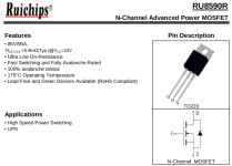
The Mosfet in the upper right corner goes to the charge connection. It is a RU8590R.
Yes, this one you don't have to mess with as long as your charge and discharge connections are separate.
That big blue wire is the negative side of the 58 volts power going out. Between it and the gate pin I have a 11.65 volts with the negative side on the output wire.
Sounds normal; there will be a 12v source somewhere on the BMS for the gate drive, probably sourced at the 3rd cell's positive if it's not LiFePO4, and the fourth cell's positive if it is LiFePO4. It could have a 3-pin (or other, smarter) 12v regulator (usually marked 7812 or similar) that produces this voltage instead, but probably not--this is why the bottom few cells can get killed or unbalanced vs the rest of them on packs left alone a long time without being used.
The source and drain pins are at the same voltage level as the output wire.
also normal; there will be a voltage across them when the bms is "off", though any current draw should collapse this.
If I am reading all this correctly then what I need to do is:
... unsolder or cut the gate pins (this would effectively switch OFF all the mosfets).
,,, connect the gate pins together with a wire (it could be something like 18-20 AWG because the gate does not use much power)
... add a switch between the wire and one of gate pin pads (each of those pads has a small surface mount 1/8 watt resistor next to it... the label reads 101).
The unsoldering gate pins is easy, and reversible enough. I'd go with the other method below, though.
Those resistors are 100ohm, IIRC (10 + 1 zero on the end, in ohms. 102 would be 10 + 2 zeros, etc).
Edit: The trace on the back with two hole under the left mosfet is the one that feeds the gates. It has a corresponding trace along the edge of the top of the board that the resistors are connected to.
This is the "easiest" place to put the switch--just cut the trace somewhere, and put the switch across it.
The only thing you might have to do, if it's not already built in there somewhere, is a resistor to ground (battery negative) (like 10kohm or so, maybe higher), as a pull-down to prevent the gate from "drifting" to a partially-on state. The board may already be wired like this, or the FETs may be of a type that this won't be much of a problem, so you might not have to worry about it at all.
Anyway, either method is pretty simple to test, and if it doesn't do what you want, simple to undo.

.jpg")


.jpg")
.jpg")
")