Common pack design mistakes, how to avoid?

Solder between copper and aluminum with silver solder. Good luck. First flex. Hundreds of so called silver solder .
About temps
Silver. 1575 melt temp
85% silver solder's 1450
80% 1400
75% 1350
70% 1285
That silver solder ? It's for Jeweler Or something with some % of silver and ? Anyway at that temp it's brazing.
 
Agniusm is using nickel-plated copper

https://endless-sphere.com/forums/viewtopic.php?f=14&t=63190&start=100#p1164028

And there was one example shown of tin-plating of copper:

https://endless-sphere.com/forums/viewtopic.php?f=14&t=63190&start=75#p1148497

The builder using tin-plating expressed disappointment at the finish of the parts, but I suspect they would work fine. I would not expect tin-plated parts to be shiny or pretty. Also, I would only want enough tin thickness to prevent corrosion from exposure to air and humidity.

edit: I just went back and re-read some of the posts. I now feel that copper is the way to go. Maybe even for the paralleling strips. Pure nickel strips are used by industry, but almost all of those are low-amp packs. Nickel-plated copper may be the premium option of choice in the near future, but...there are many affordable ways to apply some type of corrosion protection to copper strips, either before or after the cell connections.

I had been looking at purchasing spot-welded paralleled sub-groups, and then soldering the thick copper bars to make the series connections. That way I don't ever need to buy a spot-welder. And then I realized one of my issues with spot-welding is that any store-bought or DIY spot-welder I was considering had a variable amps in order to allow it to adjust to making a consistent weld on a variety of thicknesses of nickel strips. Rther than try to save a few pennies by using the thinnest nickel that would barely be acceptable, why not just set up for the thickest commonly available? 0.20mm seems to be common here, especially if there is a series connection between every two cells. a 20A cell only has to provide current a short distance through the nickel strip to get to the closest copper bar (of course, the copper would be sized thicker than needed). The series bar might even act as a heat sink for the current peaks in the nickel, but...the nickel would still act as a bottle-neck (un-necessary resistance)

Copper is now (and is likely to continue to be) readily available and cheap. Spot-welding copper is being explored in another thread, and I believe that is the future, because the builders who are interested in a DIY pack, are almost all also interested in high current.

In the DIY capacitive discharge (CD) spot-welder thread, there was a link to a video about taking a large transformer from a scrap microwave oven, and rewinding one end (as shown, it was MUCH easier than I imagined it would be), literally two wraps of thick cable. Since copper is so cheap, we can choose a thickness of copper sheet that is thicker than needed, and then adjust the windings on the transformer to perform good welds on that thickness, no adjustability would be needed after that.

https://www.youtube.com/watch?annot...6Am4HyJnmve&src_vid=vrlvqib94xQ&v=d5pGN6pqkyY

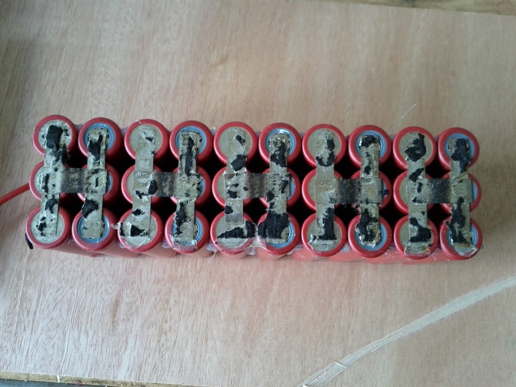
But even beyond a simple caveman transformer spot-welder, agniusm made his laser-cut copper plates that perform the function of paralleling and also series out of copper foil that was thick enough for the series connection. Of course that means that the parallel connections were from copper that was way thicker than needed, but again...copper is cheap. If someone was insistent that they wanted a thinner copper on the cell-tips (perhaps for contact area flexibility?) then it is easy to double-up on the thickness around the series connections, in the same way that we have seen controller traces beefed up.
 
I need help.

I'm making a 38S22P battery for my vectrix.

I've soldered some nikel strips. In groups of 11.

I have read that it is much better to weld the strips of nickel in series. And then solder the parallels.

How bad is it to solder the cells in series on top of the parallels?
like in the picture.

1nf4WnT.jpg


I have half soldiers and the other half without welding.

Those who do not have soldiers could stay that way. Without the 11-cell connection strips. like in the picture.

0vKozeY.jpg


For the connection of positive and negative I have thought this.

Put a strip of nikel out of the cells.

JuTUgSV.jpg


Solder a copper wire with tin. To the nikel strip that is out of the cells.

K70hom6.jpg


Solder the positive battery cable to the mitat of the nikel strip.

Z8K3dKn.jpg


Is there another better way to connect the positive cable?
 
You could just have nickel series strips go past the end of the cells a way, then fold them over the copper wire, then solder. If the copper is extra thick, the voltage drop across it will be minimal and you don't need a fancy arrangement of feeders.

See how I did it here: https://endless-sphere.com/forums/viewtopic.php?f=14&t=79324

I don't like soldering directly over the end of a cell as the heat could still damage it. Between cells and you could melt the insulation. I built one pack with soldered series connections but I kept the connections away from the centers of the cells and watched the insulation carefully. It worked out OK. Welding everything is really the best.

Remember, except for the end cells, the parallel connections between cells normally don't carry any current, or at least not much, so they can be very thin. Each cell should ideally have its own series connection to the next cell. For most 18650 cells, one strip is probably enough. The criss cross pattern would actually provide you parallel connection as well and has some redundancy, so not bad but does use more nickel.

A simpler, but maybe a bit more expensive approach would be to just cut out a large nickel sheet to cover all the cell ends in a single piece. Then just weld away. You'd need some way to locate the centers of each cell (like denting the sheet slightly).
 
Any criticism on welding layout? It's 14S4P battery. Panasonic GA(10A) cells and set for 25-30A output. 6-7.5A for each cell.
 

Attachments

  • Battery.jpg
    Battery.jpg
    215 KB · Views: 3,754
The layout looks OK, but 30A though a pair of nickel strips might be too much. You could use multiple layers of nickel (like maybe 3) to get the resistance down or possibly just solder some copper over the top of a single strip.
 
Don't pull the power out of one single point- undoes all your work. I like to solder/weld multiple smaller copper wires/strips on to the nickel (say 2-3 in your case ) in different spots and bring them out to the main lead.
 
thats what i do for better protection against a short between the groups when i arrange the cells in honeycomb shape:

0PCW25.jpg


Ytao9O.jpg


here a few pics of how i weld my packs:

QZUjLf.jpg


QVOZB1.jpg


dOIFJE.jpg


for a well balanced current flow through every single cell i do this:

JbdVJH.jpg


POropo.jpg


last but not least the shell made plastic brackets and fiberglass sheets, fuse and connectors (with antispark function):

AaVswU.jpg


q48KV6.jpg


8YY98l.jpg
 
Building packs like this is very time consuming, but with the additional protection against a short and the balanced current flow through every single cell, lifetime should be ahead compared to cheap made stuff.
Equal current flow is one of the most impartant things for a well balanced pack. If not done right, it could be that in one group of parallel cells, one cell sees for instance 10A and another 15A due to big differences in resistance. I think i must not explain that aging and wear on the cells than is not similar anymore, and sooner or later the pack will drift apart.
 
this could happen if the series sheets are to small dimensioned (or to high-ohmic) for the current flow
the pack was wrapped with foam so heat flow to outside was not good. you can see the black areas where the foam has melted and stick to the sheets.
it is ONLY 3p of low current cells (15A controller)

jAHvfC.jpg
 
Thats some battery porn there, amazing!
Do you unload the stress on the standing cells on the pottom of the pack in some way? It cannot be good if the positive side of the cell is subjected to vibration and its own weght during the ride. We have an insulator between negative and postive on the battery can so it is best to leave it alone and not stress it. So some type of battery holder is also a very good tool to use.
 
Allex said:
Thats some battery porn there, amazing!
thanks mate :)
i build my packs in view of an owner and not in view of a company. that may say all.
Do you unload the stress on the standing cells on the pottom of the pack in some way? It cannot be good if the positive side of the cell is subjected to vibration and its own weght during the ride. We have an insulator between negative and postive on the battery can so it is best to leave it alone and not stress it. So some type of battery holder is also a very good tool to use.
you are talking about the insualtion between + and - inside the cell, right? honestly, i never have thought about that..
It looks like the can is very stiff at this area and i believe it would need quite high abuse to deform the roundness.
Yes, it would not be good if the shape would always varie a tiny little bit under the own weight, or when subjected to vibrations.
This probabaly could destroy the sealing and the insulation.

On the batteries i build, i normally stick plastic angles to the outer edges by using plenty of glue. thats special glue which stays flexible. between the angles on tehe large surfaces, i glue fiber glass plates.
The side, where all the wires are soldered and routed, i put wood profiles underneath the plastic angles - mainly for getting a constant gap and seating for the plastic angles.

I don't know what may happen if i need to disasemble one of that batteries one day, but it might well be that when removing the plates, the welded sheets could come off from the cells. Furtunately there was no need to do this yet :)
 
Maddin88,

That is some excellent well thought out battery builds.....as I said before, that is why I copied your design for my build.

Are you still using .2 nickel?

Have you given any thought to using copper or brass on future battery builds to lower the resistance further? Have you tried to weld either with your DN5 (10?) that you have?

Tom
 
So after learning a lot from this thread, I'm going to have to guess this is not ideal current share...

It looks OK from one side (except for the broken off balance wire!)... Three strips for each 6p group, but then only one strip to join the oddball end cluster.

View attachment 1


But the other side all the series connects are just one nickel strip? (Oh yeah, and the other broken off balance wire.)

KIMG0112-640x360.JPG


Should this be a pack that comes on a $5400US turnkey bike?
 
Voltron said:
So after learning a lot from this thread, I'm going to have to guess this is not ideal current share...

It looks OK from one side (except for the broken off balance wire!)... Three strips for each 6p group, but then only one strip to join the oddball end cluster.
But the other side all the series connects are just one nickel strip? (Oh yeah, and the other broken off balance wire.)

Should this be a pack that comes on a $5400US turnkey bike?

Thanks for sharing the imbalanced sharing. Yes, how not to build a pack. But it was less labor to build it that way and I guess it must have worked for a while. At really low currents, the layout is less critical. If this was running at 10A or less, it might be justifiable.
 
Luckily the balance wires broke off and shut the system down before the cells died... I'm planning on cutting it up and reconfiguring it with more series connections.

It was hooked to a big Clyte DD hub in a 26 inch wheel on an 80 pound bike.

(Just to be clear, I didn't have any part in making that pack or choosing what to run it on :D )
 
atol77 said:
Hello,

What is this on the picture ??

Thanks

this is a mini-anl fuse (here 2x 100A one upon the other so 200A)
 
madin88 said:
atol77 said:
Hello,

What is this on the picture ??

Thanks

this is a mini-anl fuse (here 2x 100A one upon the other so 200A)

Those are common in car stereo systems for protection of the positive wire going to the amplifier from the battery. You can typically buy them at Walmart for $5
 
Hi all,

I'm currently in the process of building a battery pack for my FUTR Beta.

My plan it to have 7 smaller 8P subpacks, connected in series.

3S+3S+3S+3S+4S+2S+2S for a total of 20S and 8P (160 cells)

The cells I chosen is Samsung 30Qs with a max continuos current of 15A (8P x 15A=120A)
I will use 8AWG wires with XT150 connectors. And 10mm x 0,15mm nickelstrips for welding (Double or triple?)

The sub packs will have the cells arranged in a honey comp pattern using the brackets seen on the attached image and heat resistant double-sided tape to keep them in place.
subpack_small.jpg
I havent seen any other battery builds made this way. And maybe there is good reason for that. I just havent found one yet. ;)

For me there a couple of reasons I like build it this way.
- Smaller subpacks is easier to troubleshoot, and a temporary fix is to remove a misbehaving subpack. And the cells will be easier to get out.
- The Adaptto BMS has a limit of 4S per BMS module. So it will make my life easier when connecting the subpacks to BMS.
- It easier to get the more cells in to the frame and still have a good current flow within every subpack.

I like the design myself, but as I'm new to this and I feel I'm about to make a mistake. For example will the total pack performance suffer from all the extra wiring (high interna resistance) between the subpacks?

But I havent started welding yet, so please stop me before I do something stupid. And maybe help someone else so they wont make the same misstake. :)
 
You will actually want to do 4s modules instead of 3s for wiring simplicity. You would have to make a special harness to convert your 3s balance taps to 4s which would require way to many connections. My pack I built before having a MaxE was 3 separate 8s15p and when I went to a MaxE I hade to make a generally straight forward 8s to 2--4s balance wire adaptor.

Yours would be really confusing in my opinion but could be done.

23mm wide strips work great. They cover the positive and negative to make the series and parallel connections. Much cleaner and less connections. This also allows for more current draw. I used .2 mm for mine. I welded a 23mm strip on the end cells and then folded it over so it had the same current carrying capabilities.

Since I've had to replace a couple cells I'd tell you to not use tape. My next pack I'll glue the parallel cells together in a row but only the nickel (or brass or copper if I figure out how to weld that!) will hold the parallel groups together. Then tightly foam and tape the whole pack together. Then heat shrink. That will make maintenance if needed so much easier. It's always the cell in the middle that goes out....ask me how I know?

Have fun with it.

Tom
 
Maybe not the best thread to discuss spot welder strips material, please move to the appropriate place if you think it doesn't belong here.... Looking for different metal strips I found this :

https://www.aliexpress.com/store/product/SIZE-6x0-2mm-Leady-Solar-Busbar-Wire-Solder-Connection-Wires/400691_629204839.html?spm=2114.12010615.0.0.h8KLPr

What do you guys think about it as an alternative to pure nickel strips? It is a strip with a good dimensions (6 x 0.2 mm) pure copper core with solder coating. Do you think it will weld good to battery tabs and carry better current than nickel strip? Or I'm talking non sense :D It's price is also very good, much cheaper than the nickel. Would the 6 pence welder be able to weld this?
 
Back
Top