All-Axle Grin Hub motor meets Haibike FS RS 27.5

AWD,

Is there enough room for the torque arm to sit straight up against the fork? I realise that there would be no room for bolts and nuts etc... but just wondering if I got some custom machining done if it could get hidden behind there....

Also looking at your wheel, I was trying to see your lacing patter, most the spokes look like the get fed in from the inside but there a couple I think fed in from the outside. Why is this?

I was wondering myself how I would feed them myself.... It's nice like with bicycles if they just touch, but no if like with some hub motors they pushing hard against each other in the cross.

How do yours go in the cross?

cheers

edit, looking again zoomed in they all look like they were fed in from the inside.....
 
John,

In general with any wheel build, if there is an obvious chamfer of the hub spoke hole as is the case with this hub you want to have the elbow of the spoke leading out of it to decrease pressure on the radius and let the head seat against the non chamfered side. So for this hub all spokes need to feed from the inside.

I fed the second set of spokes behind the first ones because I have always done it that way. So yes there is pressure on the spokes at the cross but it is not a lot. With a smaller hub the cross is further from it and will have less pressure. As long as the wheel is properly tensioned it should not be an issue, at least it never has been for me.

Yes you could put the torque arm directly to the fork:

IMG_3039.JPG

IMG_3040.JPG

I chose to follow Grins diagram of placing the notch 50mm from the center line of the fork. If you ever had a bike with a kick back brake you might remember a similar clamping mechanism that held the torque arm for it that you had to undo in order to get the wheel off? In this case it would be difficult to feed the notch in to any type of mount on the fork due to the angle it comes in at. Setting it 50mm out it will just naturally slide right in to place.

I made another clamp yesterday using the .032 brass but used a 1" wide strip this time for a little extra strength and so it would cover the whole slot area. I still need to source a better shoulder bolt than what is available at the local hardware store but it went together well and the wheel slides in and out very easily with no tools required.

View attachment 4

IMG_3353.JPG

This forks profile is slightly ovoid and tapered but the strip was easy enough to conform to the shape. And yes a hammer, chisel and file was used! Sometimes the basic tools just do the job. I also used one of my wood working clamps to help form the strip to the legs profile

IMG_3339.JPG

IMG_3340.JPG

I don't have a proper shop at this time and was using a room in a home remodel I am doing for my son so I just was reaching for the tools on hand.

12/18

After sleeping on the idea I decided to use a double sided tape, Gorilla brand 1" clear waterproof to be exact, to better connect the clamp and the leg. I just put a layer around the bend while disassembled. I marked the proper spot with a piece of tape beforehand however and it went on easily. The extra thickness didn't interfere with my bolt holes lining up nor their length but added a bit more to the pressure that they apply. I forgot to take a picture but it doesn't look any different, just now there is less chance of it changing position due to the taper of the fork primarily. I don't think it would move without it under torque but it could get dislodged if the front wheel is off the bike for some reason like transporting it.

And Happy Holidaze btw.

 
John Bozi said:
AWD, only 3 posts, and what quality!

You are legend at providing information visually, metaphorically and in great depth.

Thank you sir :D

EDIT

You reckon that'd work for 3kw and using regen?

Thanks for the kind words John.

I'll let you know once I see if it works at 1200w using regen. At the worst you might have to use a locking bolt in place of the shoulder bolt which would require a wrench for removal but that should do the trick. There is plenty of room for a larger bolt in the 1" wide strip.
 
OK, I got everything laced in, assembled on my bike, and first test ride will start tomorrow.

I have completely disabled regen, because I find that I cannot modulate the regen as I would like to on my front wheel. Too much fear of going over the bars....

Will tell you more after the test ride tomorrow. I will also be able to take some pics with daylight then.... :mrgreen:
 
hjns said:
I have completely disabled regen, because I find that I cannot modulate the regen as I would like to on my front wheel. Too much fear of going over the bars....

:mrgreen:

I have been noodling that same quandary. Although the regen is adjustable through the CA and hopefully I can find a setting that works enough but not too much. I would really like to get it working if for nothing else than to save on brake pads.

I have been trying to find the right momentary/reed switch to attach to my brake lever and finally ordered the Bafang Sensors from Luna (https://lunacycle.com/bafang-hydraulic-and-disc-brake-sensors-e-brake-pair/) I need two anyway but have since read something that has perhaps changed my mind.

On another thread a user made the point that activating regen with your brake lever makes it feel too strong and he uses a simple button to activate it when the need arises. I am thinking that something like this would work two ways

horn__21527.1453266694.1280.1280.jpg

The green button would work as a momentary switch nicely and the on/off switch could also be connected for use as a drag brake on long steep downhills. I can mount it with another one of these to the left side hood for easy access and the same side as my front brake handle conveniently.

Image-1.jpg
 
I went against your advice with the spokes. Did anyone at grin say to feed from the inside?

To me as soon as I fed them in the natural angle the spokes stuck out was about 10 oclock, which is a large amount of bend to put into the spokes. The opposite way was almost naturally pointing to where the eyelets were...

Also the way chamfered holes perfectly fit my spoke heads....

I got a very rough bit of blue drawing on my invoice which I didn't understand too, so just went my gut instinct.... Hopefully I haven't done something majorly wrong.

https://www.facebook.com/jobozi/videos/10154634704204845/
 
I laced my wheel by feeding the spokes from the outside in. Therefore, all the elbows of the spokes are on the inside.
 
John Bozi said:
https://www.facebook.com/jobozi/videos/10154634704204845/

Did you paint the motor black? Or anodized it some way?
 
Hey you did the same as me then.

Guess what I am soooooooooooooooooooooooooooo glad I did because after mounting I realised that caliper bits clearance would have meant probably redoing it to outside in.

The heads sit flush......

I am the black sheep of the family with the only black motor made. I am guessing maybe one of the first?

Hey guys do you have 3 holes at the bearings? is that to make removal easy or maybe allow bearing heat to get air? I madly thought grin had gone at put 3 ff holes and no sealing bolts so wasted time making bolts to fit and then realised it just the bearing showing...

I can actually see the bearings even on the other side... hope dirt wont become a problem.....

I also had to file the spacers because of the bolt heads on the TArm. It was nightmare installing the wheel on a heavy bike with the spacers falling off all the time and holding up all that weight. I don't look forward to tyre changes anymore than a rear hub.... (minus a chain)

https://www.facebook.com/jobozi/videos/10154636218229845/
 
You can't believe everything you read but that bevel was pointed out to me years ago by the person that taught me how to build wheels so that is the way I did it. Yes I had to pressure the spokes some to get them to angle towards the rim but I have had to do that on every wheel I have built. Here is a screen shot from: http://www.troubleshooters.com/bicycles/wheelbuilding/


I don't know what Grins stance is but I doubt you will have any issues.
 
AWD said:
You can't believe everything you read but that bevel was pointed out to me years ago by the person that taught me how to build wheels so that is the way I did it. Yes I had to pressure the spokes some to get them to angle towards the rim but I have had to do that on every wheel I have built. Here is a screen shot from: http://www.troubleshooters.com/bicycles/wheelbuilding/
I don't know what Grins stance is but I doubt you will have any issues.

Hmm, I remember reading this somewhere. So, according to that picture, I laced my wheel the wrong way. Let's see how long my spokes will last.... :mrgreen:
 
John Bozi said:
Hey you did the same as me then. Guess what I am soooooooooooooooooooooooooooo glad I did because after mounting I realised that caliper bits clearance would have meant probably redoing it to outside in.

Hmm, for me the brake caliper has just enough space.

John Bozi said:
The heads sit flush......
I am the black sheep of the family with the only black motor made. I am guessing maybe one of the first?

I like black better than the shiny thing that I currently have. Might paint it black later.

John Bozi said:
Hey guys do you have 3 holes at the bearings? is that to make removal easy or maybe allow bearing heat to get air? I madly thought grin had gone at put 3 ff holes and no sealing bolts so wasted time making bolts to fit and then realised it just the bearing showing...
I can actually see the bearings even on the other side... hope dirt wont become a problem.....

No holes in mine that I can see.

John Bozi said:
I also had to file the spacers because of the bolt heads on the TArm. It was nightmare installing the wheel on a heavy bike with the spacers falling off all the time and holding up all that weight. I don't look forward to tyre changes anymore than a rear hub.... (minus a chain)

Hmm. I usually put the bike upside down. For the current hubbie, I gently lowered the hub + spacers into the fork. One man job.
 
OK, here is the breakdown. Warning: long post!

Assembly
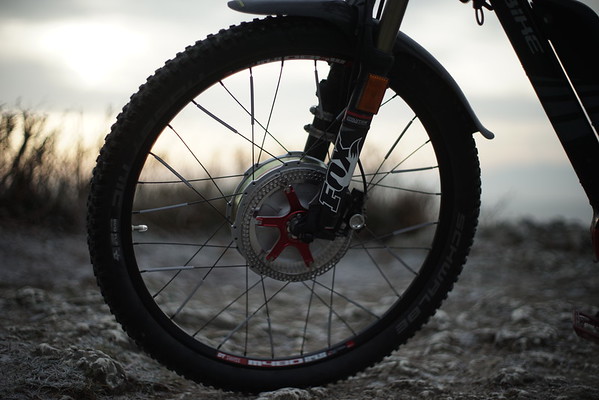
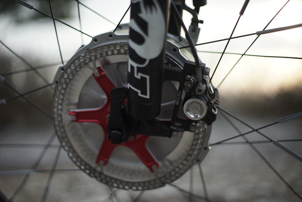
I laced the Grin Hub into my 27.5 rim. After the initial mistake mentioned earlier, lacing was relatively easy, using 2.0mm black spokes with black nipples. Then I put a nice big DH tube and a Nobby Nick tire on it. In addition, I put a 203mm Formula brake rotor on the left hand side, and the torque arm on the right hand side.

DSC01726-M.jpg


As mentioned elsewhere, I put the bike upside down, then lowered the wheel into the fork. Note that my normal front wheel also had a 203 mm rotor on it, so the only thing I had to do was loosen the screws of the brake caliper.

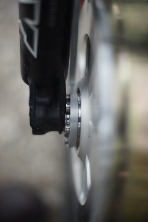
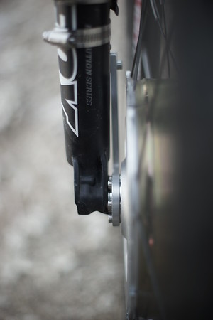
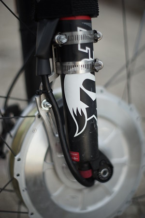
However, then I found the first „issue“. The fork is a Fox 34 with a 15mm through axle. As described earlier, I had ordered spacers for both 20mm and 15mm through axles. Obviously, I had put the 15mm spacers on. However, these spacers are not a perfect fit with the grooves in the fork that usually would guide the axle of the hub into the correct space. Instead, the Grin spacers have a bevel which is slightly larger than the fork groove, resulting in spreading of the fork legs with 2mm on each side, to allow for the Grin hub + spacers to fit within the legs, sitting on the edges of the groove. It also results in the fixation screws of the torque arm to be in direct contact with the right fork leg.

DSC01717-M.jpg

DSC01718-M.jpg


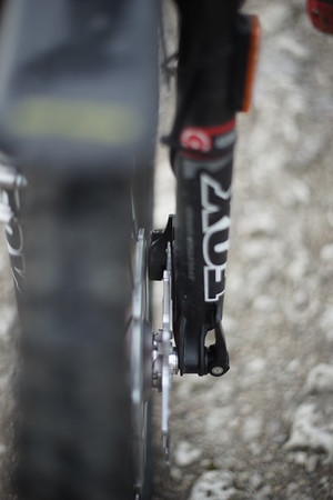
This is not a major issue, because the torque arm must be fixated to that right leg anyway. However, it is not neat, and needs some refinement. On the other side, the brake caliper (Formula R0) has about a millimeter space. That’s more than sufficient.

DSC01719-M.jpg

DSC01728-M.jpg


In addition, I used a Grin rear torque arm fixator, using metal fixators to keep the torque arm in place. Then I guided the phase/hall/temp wires over this, wrapped in some (unshrunken, else replacing the tire is a lot of hassle) shrink wrap and some tie wraps.

DSC01716-M.jpg


In the end, with the 4mm widening of the legs, but with the 15mm through axle firmly fixating the wheel inside the legs, I find no real issue with the suspension capabilities of my fork. Then again, with my first test ride I was very careful and did not push the system very hard. More on that later.

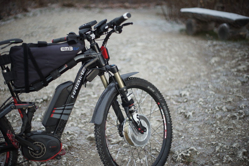
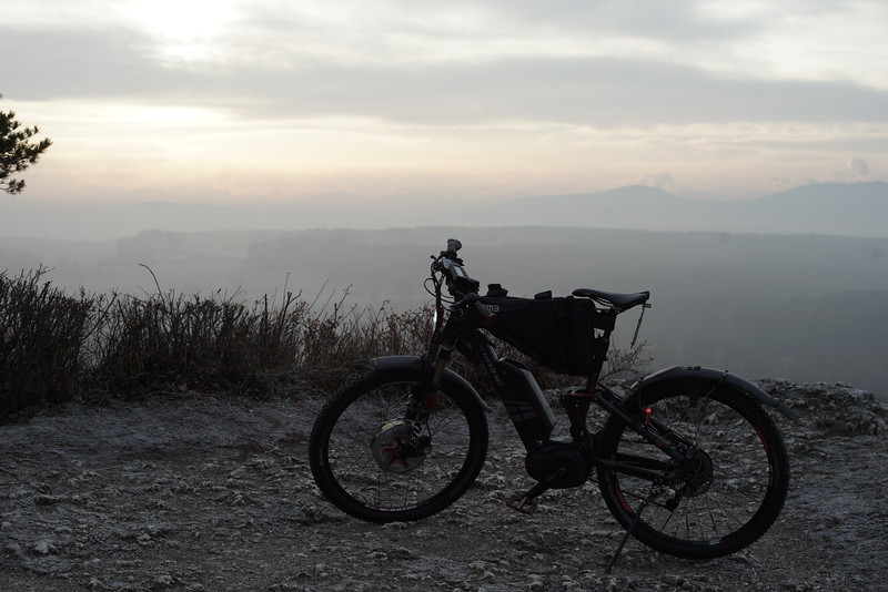
Once the Grin hub was in, I put the bike upright again and fixated the extra battery. As you can see, the standard battery is already within the triangle, leaving no room for the additional battery within the triangle. As I do not want the second system to interfere in any way with the first system, I put my EM3EV battery in its default battery housing (bag) on top of the triangle. The EM3EV bag comes with some great lengthy fixators, allowing for a firm fixation of the bag on top of the triangle. In addition, the bag is a bit bigger than the battery, so I can hide some of the wires inside.

DSC01720-L.jpg


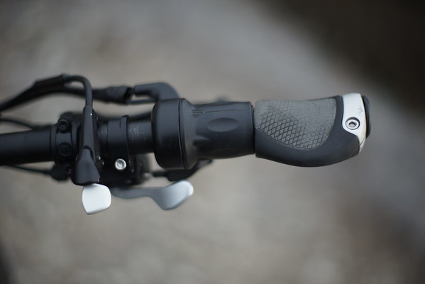
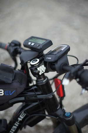
Once the battery was added, I fixated the Cav3 on the steering bar using the default fixator, added the throttle on the right side of the bar, and put the PhaseRunner just under the triangle right behind the fork, using a couple of tie wraps. Then I put some shrink wrap over the visible wires (without shrinking them) and tied everything tight, again using tie wraps.

The CAv3 is configured for torque throttle limited at 50A 2500W. So this morning it was time for a test ride.

DSC01722-M.jpg

DSC01721-M.jpg


Test ride
Summary: so now we have a fully MTB, with a midmotor, a heavy front motor, and with two batteries, one of which is riding quite high. Estimated total weight (excluding rider) is in the 45kg or so. Not surprising, this is actually NOT a nice MTB to go downhill with. Going up, however, is a completely different matter!

So behind my house, there is this nice hill. From my house (around 370m altitude) to the top of the hill (around 780m) are various forest roads. I started by riding one to the top. What I found is that I had to be really careful to keep traction on the front wheel. Essentially, on a forest road with leaves and stones and a 10-15% inclination, 1kW on the front with 350W on the rear is already a recipe for loss of traction. 500W on the front is the maximum for me, with a total speed around 15-20km/h. However, that is already a huge improvement over my previous state (RWD only), because with the 350W on the RW only, I got around 8-10km/h. In other words, going uphill is really nice! And what is even better, it is near soundless! With my previous 8kW Cromotor configuration, all the animals could hear me coming. With the current configuration, I came up to 5m of a marsh harrier, before it sighted my front light, and decided to go airborne. A deer saw me from 20m away, and then fled. It is really really nice!

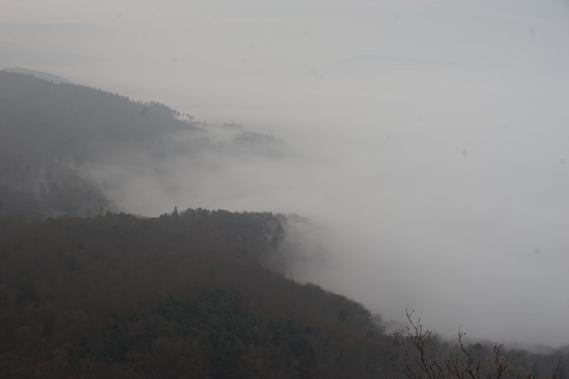
And on top, it was even nicer!

DSC01724-L.jpg

DSC01725-L.jpg


OK, now the bad part. Going downhill with such a heavy bike and such a big lump on the front axis is not nice. I will not try to do any small jumps, because I won’t be able to keep my balance correctly, whereas with the original 31kg Haibike middrive configuration this is quite feasible. There are some tarmac roads that I went down where regen would have worked, but when going down a forest road, using regen is not enough modulation to prevent dangerous loss of traction up front. No go for me.

So, will this work for a mountain bike? Only if you drastically change your expectations of MTB-ing. See it as being able to go offroad with a luxury SUV, that most of the time is used for commuting. Nice enough.

If it is exercise you want, skip the whole electronic motor thing. I have another MTB (without motor) just for that.

But then where does this combo (Mid drive + Front Grin hub) excel? On tarmac, as a commuter. I love it. I love the acceleration up to my comfortable cruise speed (45km/h). I love the possibility to temporarily lighten my work load by just moving the throttle. And I love that I can take this bike to work and home again every single day, preventing me to burn gas with my car or getting diseases in public transport. So it is fully worth it!

DSC01713-L.jpg
 
hjns said:
AWD said:
You can't believe everything you read but that bevel was pointed out to me years ago by the person that taught me how to build wheels so that is the way I did it. Yes I had to pressure the spokes some to get them to angle towards the rim but I have had to do that on every wheel I have built. Here is a screen shot from: http://www.troubleshooters.com/bicycles/wheelbuilding/
I don't know what Grins stance is but I doubt you will have any issues.

Hmm, I remember reading this somewhere. So, according to that picture, I laced my wheel the wrong way. Let's see how long my spokes will last.... :mrgreen:

I really don't think it will matter in the long run Henk. Especially the shorter the spokes are for smaller rim diameters.
 
hjns said:
OK, here is the breakdown. Warning: long post!

So, will this work for a mountain bike? Only if you drastically change your expectations of MTB-ing. See it as being able to go offroad with a luxury SUV, that most of the time is used for commuting. Nice enough.

If it is exercise you want, skip the whole electronic motor thing. I have another MTB (without motor) just for that.

But then where does this combo (Mid drive + Front Grin hub) excel? On tarmac, as a commuter. I love it. I love the acceleration up to my comfortable cruise speed (45km/h). I love the possibility to temporarily lighten my work load by just moving the throttle. And I love that I can take this bike to work and home again every single day, preventing me to burn gas with my car or getting diseases in public transport. So it is fully worth it!

DSC01713-L.jpg

Nice write up and vistas but isn't there supposed to be snow there this time of year?

I also had an issue with the 9mm adapter being too big to easily fit in a standard dropout and notified Grin of this. Fitting the stock wheel there is even a little slop until the QR is tightened down. And I thought I had filed my last drop out, maybe next time!

I have also found that you can't go roaring up steep loose terrain with a front hub motor but at lower speeds and using the right low gear in the rear and pedaling along balancing between the two it is pretty much unstoppable. And lots of fun. I considered putting this motor on my hardtail mtb but I have found that at this time I don't live close enough to any real single track and the little I find myself on it seems like the narrower tires I use at a low psi works for my needs. My primary use is enough pavé to get to gravé and avoid as much traffic as possible.
 
great write up suitable for a magazine :)

I wasn't that happy with how my 20mm sat. One side had lip to stay in place but the other had nothing holding or was a fraction too loose. I had cloth tape them on and then lift the wheel in..... I have a heavy bike that you cant just flip upside down, would probably break the seat or other stuff on handle bars....

The phase runner and this motor together are just amazingly silent. I could hear it when testing, but out in the open riding I literally can't hear anything other than new knobbs on bitumen.

Jumps? definitely out for me, after spending this much money, that parts out.

depending on your chemistry, there are better places for your battery than up there. I know I could fit probably 10ah 12s easily in your triangle around the rest of the stuff with a few alu trays and tube clamps.

NOtes on spoke discussion, I totally trusted the advice awd gave. The explanation totally makes sense too. However, I don't believe Chinese hub motor designers are always right. Still the fact that you have a lot more hugging of material is super important especially for our weight demands, but the bend for our applications and the lack of clearance for the caliper is enough for me to do the same if I had to spoke it again at least the disc brake side.

finally, to where I'm at I plugged my regen button into CA into "ebrake" plug and the ca registers the graphic but I'm getting no braking. any ideas?
 
I was under the impression that Justin had a big part in designing this? So it would be good to see what his view on the spoke feed is in relation to the chamfer. I can see that on your wheel John that your spokes are shorter than mine and I think you made the right choice. I don't have any clearance issues with my caliper or torque arm bolts either, just the 9mm adaptors were a bit large, and I am not talking much either.

Although I have a good work stand if I am going to take off the motor I always opt for flipping it upside down also. I just have to rotate the CA and headlight out of the way and my overall setup is pretty light too.

I haven't had time to do the final push and was waiting for my Schlumpf chamfer tool to come back to me anyway which arrived today. The big chainring goes above the shark style battery I have and only would allow the use of a few of the higher gears. With my Schlumpf it will not be a problem and I can ditch the front derailleur also. I have a high speed drive on my black bike but I got a bit larger chainring for my speed drive that will get me up in the gear range I want so as to be able to pedal with good resistance at speed.

Keep up the good work and thanks for sharing!
 
John Bozi said:
However, I don't believe Chinese hub motor designers are always right.

To quote myself, I was referring to many bike concepts that don't translate into ebike components. I have followed bicycle ways of doing things with spokes which created way to much pressure on the cross for example.

As for Grin design, and anyone designing diy components there will always be compatability that you just can't please everyone.

So take my comment with a pinch of salt, slice of lime and etc... My mind is all over the shop.

I have got my temperature sensor working, now and we are in the middle of summer. Over 30 degrees C and the motor heats very very quickly.

I also guess there are settings in the phase runner that are limiting torque handling in an incredibly unusual way. The set up as it is now will bog down very quickly on pretty mild inclines if at low speed.

Still can't work out how to get more than 22a running. But with the heat already high I am not sure I should be running higher than 1.8kw as I am limited now.
 
Heat is not good. It isn't that hot here, and rarely even gets close to that, but I will have the temp gauge going for sure.

These are beta units and there are some issues but that is why they did a beta program and I am glad to support that as I see a future for this hub. I have been emailing Grin with anything that I thought would help them along and I hope that others are doing the same.

I don't think we have seen a picture of you bike yet John?
 
Success! But I have a saying that I go by "nothing is ever stock" and it was proven once again. Sure it would be easier to just walk in to a shop and buy something but not nearly as educational and satisfying as spacing and doing a build. Only got a ride around the block in as it was dark and foggy and I was in town. Will get a better feel for it tomorrow.

Rolling chassis completed during my lunch break, remove old cranks and derailleur/cable and chamfer the bb for the Schlumpf.

unnamed.jpg

Pre ride. Most cables tied down the upper ones are still a bit of a rats nest. Need to shorten the throttle cable and make a temp cable and tidy that up.

unnamed.png

Aprés ride:

unnamed-2.png

Had to build up the Solstice fire to celebrate!


And Happy Solstice btw. We had our annual fire to celebrate the Yule season.
 
And btw. The torque arm clamp works just fine at 1200+W. I did a roll back and goose it test on a hill and it stayed exactly how I had it set. The 4mm long shoulder bolt I am using could be a little shorter even but not easy to source but at least I finally found one that is stainless steel. Makes taking the wheel on and off very easy and tool less which was my goal.

No clearance issues but the bolt holding on the inner pad adjustment wheel on the Avid bb7 brake caliper is pretty close to the motor housing but not enough to worry about. I could see some issues with other calipers though perhaps.
 
great follow info guys, some spectacular hd pics there too.

I am running 4 hose clamps with a rectangular bit of tube as a spacer between the TA and fork Arm. I have noticed that there has been a slight movement of the spacer... This is at 1.8kw.

I have also noticed that heat transfers from the motor to the axle and fork.... 100c should not be an issue and it would never get to that that far.

I ordered yesterday and received today the programming cable from RS very happy with there speed and free delivery. $35 au all up is good....

so now to downloading and programming.....

I do know however if I get regen working that slight movement will most probably become larger to and fro movement so will test and customise eventually if I think its worth it at all - since heat in summer is an issue and extra watts from regen are not always worth it....
 
Back
Top