You are using an out of date browser. It may not display this or other websites correctly.
You should upgrade or use an alternative browser.
You should upgrade or use an alternative browser.
Idiots guide to rewinding Revolt 120 pro
- Thread starter larsb
- Start date
Wheazel
10 kW
Miles said:Lars,
I have a coil of the wire that you're intending to use.
It measures 2.65mm x 1.35mm including the insulation.
I could send you a piece to play with, if that would help.
That's a kind and helpful offer!
Have you wound many stators with that type and size of wire?
What tools and procedure would you advice?
larsb
1 MW
@Miles: A piece of the wire would be super, then i can try before i order the full length. I will send a PM with adress.
I would also like to know if you have wound with this wire and how tough it is to work with. Can you recommend it?
On a slightly different note: I've read your inrunner threads, interesting stuff and on a very high level, what is the status on these now?
I would also like to know if you have wound with this wire and how tough it is to work with. Can you recommend it?
On a slightly different note: I've read your inrunner threads, interesting stuff and on a very high level, what is the status on these now?
Lars,
PM me your address and I'll put a piece in the post.
I bought some to see if it would be feasible to wind my 36t inrunner with. It wasn't. Inrunners are more tricky to wind than outrunners. They usually require greater manipulation of the wire so, work hardening of the copper is more of an issue. It may be fine to use for your RV 120, the bend radii for this are greater etc.... It would be wise to get a feel for the wire before ordering, though.
With regard to the inrunner design, I have one in construction. The case and rotor are made, the stator lamination stack is made. I'll have more time to work on it again in February.
I don't have much winding experience, I'm afraid. The 2:1 ratio wire is definitely easier to work with than square wire, which does its own thing despite your best efforts to keep it from twisting.....Wheazel said:Have you wound many stators with that type and size of wire?
What tools and procedure would you advice?
larsb
1 MW
I will make a tool for the opening of the motor, Revolt is recommending a workshop press for the job but i will make a simple screw jig to remove the covers.
See this:
http://www.revolt.org.il/articlepage/how-to-open-the-motor/
Tips or how-to:s appreciated from those of you that have opened a revolt motor. How did you open/was it difficult/what kind of forces?
See this:
http://www.revolt.org.il/articlepage/how-to-open-the-motor/
Tips or how-to:s appreciated from those of you that have opened a revolt motor. How did you open/was it difficult/what kind of forces?
larsb
1 MW
I needed to decide which motor to rewind so i hooked the new motor up. Auto identify worked after two tries (which it never did on my old motor) and the sound of the new motor is a lot better. I think the main issue with the first motor is bad hall placement.
After all: that the controller doesn't find correct combination during auto identify and the manual setting on the adaptto is best on -24 degrees means that the sensors are 24 degrees off. And that also means that hall 1, 2&3 might be off between them by +/-20 something degrees.
I will mount the new motor and rewind my old one. I really hate poor quality! Some things should never be manufactured as they are a waste of resources.
sn0wchyld
100 kW
larsb said:I needed to decide which motor to rewind so i hooked the new motor up. Auto identify worked after two tries (which it never did on my old motor) and the sound of the new motor is a lot better. I think the main issue with the first motor is bad hall placement.
After all: that the controller doesn't find correct combination during auto identify and the manual setting on the adaptto is best on -24 degrees means that the sensors are 24 degrees off. And that also means that hall 1, 2&3 might be off between them by +/-20 something degrees.
I will mount the new motor and rewind my old one. I really hate poor quality! Some things should never be manufactured as they are a waste of resources.
yep, makes me wonder if i should (at the very lest) replace the halls on my revolt. I do occasionally get cases where the motor starts braking rather than accelerating (ie controler output off by about 180deg!!) which im putting down to bad halls. Rare enough however to not be a big issue. Shame, the general design/size is perfect for ebikes, but the quality isn't even up to china standards... might just get a new motor (LR bigblock looks about right...)
larsb
1 MW
Karolis
10 W
What I found with my RV 160 that this leakage is only when motor is assembled. Take the rotor apart from stator and nothing will stick to rotor. Also what i mentioned earlier, this rotor's casing is not even round, It is more like oval shape with more metal on one side than over. it is out of balance in big way.
larsb
1 MW
I saw the rotor pictures that you linked. That's a a real shame, Revolt should have scrapped it if they had any quality control. Mine is not that bad.
It's easy to bend some mild steel just to try a flux jacket, measure the kV afterwards. I think i'll do it but not now. I will concentrate on the rewind.
The opening jig is ready, will open motor in the week that comes.
It's easy to bend some mild steel just to try a flux jacket, measure the kV afterwards. I think i'll do it but not now. I will concentrate on the rewind.
The opening jig is ready, will open motor in the week that comes.
Wheazel
10 kW
Oh boy I wanna see the results of the rewind now! Or more like yesterday!
I saw that getting 1kg of the wire you are going for cost about 50Euro.
Tempted, even though I don't really have the time at the moment.
I just remember the joy of building my own motors from scrapped cd roms etc.
Some of them became workhorses on small rc planes, and others failed from various design flaws.
The life of a 15yo electronics noob with a passion for rc planes in the late 90s
Please weigh the copper that you take off the stator for reference!
larsb
1 MW
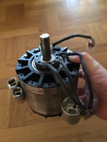
I removed rotor tonight, it was easy with the jig. I am a little surprised at how strong the magnet forces are, after the removal of all mechanical contact it was still needed to continue pulling with the jig to get the rotor completely off.
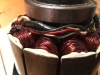
Windings look shorted and burnt on spots beneath the hall cables.
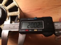
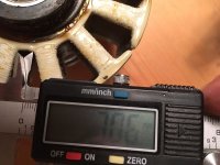
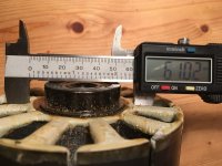
Rotor is round and has an even thickness. You can see the modified M10 bolts that was used for pulling in the pic.
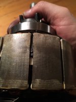
Hall sensor placement is slightly off on one sensor (2nd pic). It's not a lot but i think also that they should be moved closer to the magnets to be switched better. That will require grinding some slots in the stator.
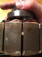
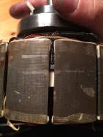
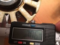
EDIT:The pictures show a surprise: laminations are 0.5mm, NOT 0.2mm
Windings look shorted and burnt on spots beneath the hall cables.

Rotor is round and has an even thickness. You can see the modified M10 bolts that was used for pulling in the pic.

Hall sensor placement is slightly off on one sensor (2nd pic). It's not a lot but i think also that they should be moved closer to the magnets to be switched better. That will require grinding some slots in the stator.


EDIT:The pictures show a surprise: laminations are 0.5mm, NOT 0.2mm
eee291
100 kW
can't wait to see the results!
Wheazel
10 kW
Nice pictures, I am curious to what you do at work/hobbies to beat up your fingertips like that 
larsb
1 MW
I work in engineering (in an office). The fingers are more hobby related, I had a small accident with some home brew explosives when i was younger, it blew the skin right off three fingers. They haven't been the same ever since 
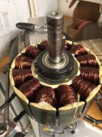
I tried to remove shaft tonight but did not succeed. Heated stator to 125 degrees, removed circlip and pushed with a bearing puller but the shaft stayed in place. Bearing glue is visible on the edge of the bearings, i will try to heat with a torch tomorrow.
Bearings could not stand the side load so i will have to replace them. In the end i decided to pull off the rear end cover without the shaft to be able to see the rear windings. That was no problem at all.
Windings are covered with enamel or epoxy and will have to be heated to be able to remove them.

Ohbse
10 kW
Good stuff, very interested to see how you get on. The numbers for potential improvements are pretty incredible!
larsb
1 MW
I got the shaft out yesterday, some torching was required and some thinking 
My shaft is 5/8" instead of 15mm in the drive end to fit kart sprockets. That means the shaft must be pushed to the drive direction instead of towards the other end as is recommended in revolt instruction.
When i realised this it was easy enough to remove the shaft. For anyone attempting to open a revolt motor: i would just remove the covers and leave the shaft in place if bearings don't need replacement if i did it again.
larsb
1 MW
1.5 hours later.. Some teeth could be unwound relatively easy, two or three had wires that needed to be cut to pieces and heated with soldering iron to be able to remove them due to the enamel/epoxy glue.
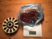
Original stator winding:
Copper weight 420g/0.93lbs
Winding length per tooth ~150cm/59" (x5 parallel wires and 12 teeth gives total wire length)
0.8mm/ 20-21 awg wire.
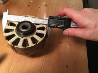
Stator length 45mm.
(Edit: 50.8 / 2" is magnet length, i got these mixed up)
I will measure the slots tomorrow, interesting to see how close i was with my first measurements.
@Miles: your wire turned up today by the way, thanks! I will try a rewind of one tooth with that. The wire is quite stiff so i wonder how precise i can wind it..
Ohbse
10 kW
From the looks of the slots compared with your original diagram they might be even larger than you had modeled!
Very interested to hear of your progress, I've heard from many people around here re-winding is pretty hard work.
Very interested to hear of your progress, I've heard from many people around here re-winding is pretty hard work.
larsb
1 MW
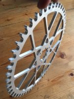
999zip999
100 TW
That is art. If you're not going to use it I would love to hang on my wall.
larsb
1 MW
Wheazel
10 kW
Looks like thick endcaps on the the stack. Thats good for avoiding shorts.
Before you try rewinding the thicker wire, I advice you make sure to have some wedges and stuff to push and shape the wire.
You cant pull the arc of a thick wire straight inside the slot. It is a challenge to get the wire flush against the teeth.
Before you try rewinding the thicker wire, I advice you make sure to have some wedges and stuff to push and shape the wire.
You cant pull the arc of a thick wire straight inside the slot. It is a challenge to get the wire flush against the teeth.
Similar threads
- Replies
- 12
- Views
- 10,394
- Replies
- 96
- Views
- 9,586
- Replies
- 9
- Views
- 5,290


