Comparing Two Same Motors with Different Kv's

markz

100 TW
Joined
Jan 9, 2014
Messages
12,179
Location
Canada and the USA
I tend to learn better when I write things out, and I stumbled on the whole Kv torque myth last night. I caught myself quickly though. I just have a quick question and please tell me if I did the motor sim and explanation correctly.

On the motor simulator I am choosing the MXUS 3000W 4506 and 4503.
Here are the quick notes.
MXUS 3000W 4506 is 45mm stator and 6T (x10) has a Kv of 11.9
MXUS 3000W 4503 is 45mm stator and 3T (x21) has a Kv of 6.0

I have no idea if these 2 motors have the same "copper fill"
Is it just a matter of 3x21=63 and 6x10=60 ?
What does that mean exactly? 3 turns of 21 strands and 6 turns of 10 strands?
*If that be the case maybe I should have picked two motors with different Kv's but same copper fill.

Here are the references.
https://endless-sphere.com/forums/viewtopic.php?f=30&t=63142&hilit=mxus#p944431

21X3T Winding
Phase resistance = 0.072 Ohms
RPM at 50V = 597, 11.9 Kv
1.78A/89.4 Watts, No Load

16X4T Winding
Phase resistance = 0.110 Ohms
RPM at 50V = 448, 8.9 Kv
1.08A/54.2 Watts, No Load

12X5T Winding
Phase resistance = 0.163 Ohms
RPM at 50V = 359, 7.1 Kv
0.84A/42.2 Watts, No Load

10X6T Winding
Phase resistance = 0.225 Ohms
RPM at 50V = 299, 6.0 Kv
0.64A/32.1 Watts, No Load

All bare hub motors (no spokes or rim) weigh in at right around 9.14 Kg / 20.2-lbs

According to Justin's data, Teslanv get the following phase current limits on the various windings:

MXUS XF40-45H "3000W" Direct Drive Hub Motor Series:

3T:
Max. Continuous Phase Current: 55A
Overheat in 10 Minutes: 85A
Overheat in 60 seconds: 242A

4T:
Max. Continuous Phase Current: 42.6A
Overheat in 10 minutes: 66A
Overheat in 60 seconds: 186A

5T:
Max. Continuous Phase Current: 34.9A
Overheat in 10 minutes: 51.6A
Overheat in 60 seconds: 150A

6T:
Max. Continuous Phase Current: 30.3A
Overheat in 10 minutes: 47A
Overheat in 60 seconds: 132A

Generic Winding Phase Current Limits per strand:
Max. Continuous Phase Current: 2.84A per strand
Overheat in 10 minutes: 4.4A per strand
Overheat in 60 seconds: 12.4A per strand

*All data assumes a non-vented hub motor. Venting or other methods of cooling should increase these values.

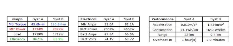
To match up the 2 motors and debunk the myth of a higher turn count motor having higher torque, which is false. The truth is they have the same and I think the key term there is "with the same copper fill" which is why I asked my questions. I did this in the first motor simulator. Then change 4503 to 16" wheel and the overheat time is 41 minutes compared to 2.9 minutes, picture #2 below.

To get the torque lines the same - I decreased the controller resistance in System A 4503, and decreased the System B 4506 controller amps. Decrease the throttle in System A 4503 and the graph matches up.

The 4503 has thicker and shorter wire which can take more amps, as seen in the quote above. That is why I decreased the resistance in the motor simulator for 4503. The 4506 has thinner and longer wire which increases the resistance (increases the heat, and heat by itself increases resistance) which does not allow for more amps so the motor would over heat quicker when its given more amps.

I think another characteristic to look at is the torque curve, the 4506 falls off sooner and has a lower speed where the red meets the black line. Also an interesting note is to see the efficiency.

A good way to go, I believe is to go with the 4503 that gives you a higher speed, but decrease the wheel diameter which reduces the speed but allows you to keep the motor running cool when pushing amps.

The argument to that fact is when you have a smaller wheel diameter say a 20" as apposed to a 26" or 29", you dont get good maneuverability to roll over pot holes for example. But the downside to going 29" is the motor would over heat faster as seen in the graphs below which I will leave in the attachments.

You have to take into consideration if you are building a system from scratch, so you can pick and choose the motor wind, controller, wheel size, the speed you want, then look at your riding style, are you riding on flat or hilly streets, or is it stop and go commuter, maybe its trail riding.


View attachment 4
View attachment 1
comparingnotes.jpg
 

Attachments

  • 2.jpg
    2.jpg
    21.7 KB · Views: 1,700
Right I was pondering the same thing. From what I can tell, a low turn motor can produce the same MAX torque as a a high turn motor given they have the same copper fill. The only difference is the current necessary to produce the torque.

So if we have a 48V pack and a motor controller pushing say a 15A phase current, the high turn motor will produce more torque at that current. However the low turn motor can take more current and at its overheat current will produce the same max torque as the low turn motor at its overheat current.

Is this correct, or have I just been sniffing too much glue.

Thanks
Lonnie
 
Subbed.
I want to learn too.

I still wonder why my 100 gram 1000kv motor can handle 250 watts for 30 minutes straight and come out slightly warm but my 2700 gram 10kv BLDC motor can't handle 250 watts for more than a few minutes without overheating.

Is this a "horsepower sells cars, torque wins races" thing?
 
parajared - I think that is due to the mass of the motor and its ability to shed the heat. Also when I was comparing the big Crystalyte motors, there is an aspect of the design as well, like how the tooth is cut and if the windings are compressed where they come out of the slot. That part is totally noticable when you open up the motor.

lonnie776 - Yes I believe so
The only difference is the current necessary to produce the torque.

Also found this

Nice summation below.
https://endless-sphere.com/forums/viewtopic.php?f=3&t=58490&p=1254154&hilit=torque+per+amp#p1254154
The "power" and "torque" capability of the motor is not changed by different windings. The torque per watt of heating comes from the mechanical properties like radius, width, gap, permanent magnet strength, and this heating together with the heat dissipation capacity of the motor determine the max continuous and short term torque capability of the motor.

The power that is applied to the motor does vary depending on the voltage and current (and the back EMF from the RPM), but the motor's torque per unit heat is fixed.

The easy thing for them to do is to change the windings, which merely changes the RPM per volt and the torque per amp, and compensates for voltage and wheel size. d8veh said this several times by stating the 36V 20A setup was comparable to the 48V 15A.


https://endless-sphere.com/forums/viewtopic.php?f=2&t=14416#p215317
Larger motors have more mass to absorb and shed more continuous-heat/temporary-excess-heat. A larger diameter motor will automatically have more leverage and torque per the same watts put into it.
^Makes sense
 
Here's the original post by Kingfish which spawned a heated debate: https://endless-sphere.com/forums/viewtopic.php?f=2&t=64907

To simplify, here are a few key concepts you should understand:

For a given motor design and stator width:

Kv (RPM per Volt) and Kt (Torque per Amp) are inversely related, and Multiplying Kv and Kt gives a CONSTANT for all motors. Here is the equation:


Motor windings are usually made with small diameter magnet wire. Often this is 0.5mm diameter wire. (This is one strand.)

To get large cross-sectional area for a motor winding, manufacturers make a bundle of wires in parallel, instead of thicker wire, which is harder to bend.

For the MXUS motors, the common winding options are:

21x3T
16X4T
12x5T
10X6T

Multiplying the two numbers in each winding option will tell you the total strands of copper fill in the winding:

21X3T = 63 Strands
16X4T = 64 Strands (Highest Copper Fill)
12X5T = 60 Strands
10X6T = 60 Strands

Per the above, the 4T has the highest copper fill, and can technically produce the most TOTAL torque.

But there's more.

Remember that Kt is a measure of Torque per amp.

In the above windings, the 6T winding has the highest Kt (Torque constant), and in fact, a 6T winding has twice the Kt, and one half the Kv of the 3T winding. The Kt and Kv of a motor are each exactly proportional to the number of turns around each stator tooth.

So how can the 3T motor produce the same total torque as the 6T, if I just said the 6T has twice the torque constant?

The answer lies in the number of strands in parallel within the winding.

The 3T winding has twice (actually one more than twice) the number of stands in parallel. This allows the 3T winding to take TWICE the current as the 6T winding, with roughly the same loss from resistance and the same thermal results.

So what does all this mean in the real world?

A 3T winding can produce the same total torque as a 6T winding, but it needs twice the current (And a larger controller than can put out twice the current) of the 6T winding to do so. Also the phase wires need to be twice as large on the 3T winding for a fair comparison.

On the flip side, the 3T winding has twice the Kv (RPM per volt) as the 6T winding. So at 48V, the 3T will spin (unloaded) at about 12*48 = 576 RPM, whereas the 6T winding will spin at 1/2 of that speed (6X48 = 288 RPM). However if you double the voltage to 96V, the 6T motor will spin the same RPM as the 3T motor on 48V.

When you are deciding on components for your bike, you have to take in all of these variables to decide what voltage, and what current you want to use in conjunction with the winding of motor to achieve your desired top speed.

Wheel diameter is a separate discussion, but affects torque, top speed and overall efficiency. Generally, it's better to run as small of tire (wheel) as is feasible given the intended terrain. Smaller wheels will always equal more torque and higher efficiency. Surprisingly, the smaller diameter tire does not affect top speed as much as one would expect. This is mainly because of the better efficiency.

With that being said, if you want a large tire, it is my opinion that a lower Kv / higher Kt winding is preferable, although many would argue that it doesn't matter, so long as the voltage is appropriate.
 
Yeah that sums it up nicely. I just read a few posts in that thread you linked to and I think the choice boils down to your riding style. I do remember that thread, I read it 100 times, I will have another go at it for sure. Be nice to have it freshly posted somewhere without having to read through it all to get the basics down you know what I mean.

What tripped me up on the motor simulator was I kept seeing a huge Torque curve between the 5403 and 5406. It's done that several times now and I know better to think the High Speed and High Torque bullshit, but its still propagated.

A power beast speed monster go with low turn high kv. Be sure you got the right controller for that though, a high discharge one.

Stop and go all the time high turn low kv.

Somewhere in between, then a middle of the road turn and kv.

This matches up 100%. Just changed throttle and controller resistance.
 
First decide a vehicle speed range you want performance across.
Then decide a controller (because motors are much easier to get custom windings).
When maxing out whatever the controllers voltage ceiling is as BEMF from your motor at peak vehicle design speed (or say 20-25% lower than peak speed for field-weakening controllers), you can work backwards to arrive at the motor Kv that best suits your needs.

You don't want a pointlessly high kV, because it costs you torque for a given controller phase current limit, but may also want high speed capabilities. This can be done and is my personal favorite approach to EV performance, but it requires a controller capable of big phase currents or the vehicle will feel weak and eat cheap controllers.
 
Thanks Teslanv,

Correct me if I'm wrong but it seems like you are just saying in a really roundabout way that motor rpm dictates torque. Like a 24 volt 20kv motor is the same thing as a 48 volt 10kv motor of the same copper fill because they are both 480 rpm motors. Is that correct?

Assuming that is true I think this answers my question of why my 100 gram motor and my 2700 gram motor both perform at 250 watts. My 480 rpm application requires enough torque to get my fat butt down the road whereas my 15,000 rpm application only needs enough torque to fly my model airplane.
 
parajared said:
Thanks Teslanv,

Correct me if I'm wrong but it seems like you are just saying in a really roundabout way that motor rpm dictates torque. Like a 24 volt 20kv motor is the same thing as a 48 volt 10kv motor of the same copper fill because they are both 480 rpm motors. Is that correct?

Assuming that is true I think this answers my question of why my 100 gram motor and my 2700 gram motor both perform at 250 watts. My 480 rpm application requires enough torque to get my fat butt down the road whereas my 15,000 rpm application only needs enough torque to fly my model airplane.

ehhh. not exactly.

What I'm saying is that for a given motor design, (Same stator construction, width & diameter, etc., with the only difference being the winding pattern) the Kv (RPM per Volt) and Kt (Torque per Amp) will vary, and both values are proportional to the number of "Turns". Also, Kv and Kt are inversely related. (You can't have high Kv AND high Kt for a given design, it's one or the other.) - But the High Kv winding will always have a greater cross-sectional area of winding, and can thus make equivalent total torque as the high Kt winding because it can take more current without overheating that the high Kt winding can.
 
Another way to say it, the magnetic field makes the torque. The field is made by current times the number of turns. So 6 turns with 50 amps makes the same field as 3 turns with 100 amps (both are 300 amp-turns). The Kv and Kt will be different (the voltages and currents required), but the same power input will produce the same torque and the same heat.

This is assuming the same motor and copper fill, changing only the winding configuration.

The same total fill requires the same total cross section of copper in each slot, however the cross section of each turn will vary with Kv and Kt.
 
I seem to remember that max efficiency is somewhere around 80% of the unloaded RPMs. So...decide top speed (loaded), then pic wheel diameter, add 20% to the wheel RPMs, so you will have an RPM range to shoot for. Then...you can juggle voltage and Kv.

Confused yet? Research field weakening to get higher RPMs without changing Kv or voltage, but less torque at the top end...
 
Confused yet? Research field weakening to get higher RPMs without changing Kv or voltage, but less torque at the top end...

Yeah if I ever feel like I'm getting a bit too cocky, a little too brazen about my knowledge base, BLDC motor theory or some chit-chat about space time always helps put me back in my place.

So its the flow of amperage (not say wattage) that dictates the strength of the electrical current running through the wires, that increases the electrical "gauss" if you will, the force that repels the neodymium magnets and you the correct lingo for gauss is "amp-turns" in the BLDC industry because the same repulsion force can be attained through a summation of amperage + turns and not just by merit of amperage alone?

So with my 250 watt airplane motor I'm not producing the same "amp turns", I don't have as large of magnets, I'm not producing as strong of a field as my 250 watt e-bike motor and that's why my rc motor is light and my e-bike motor is heavy?
 
Field weakening
The speed of a DC motor can be increased by field weakening. This is done by inserting shunt or diverter resistances in parallel with the field winding. When the field is weakened, the back-emf reduces, so a larger current flows through the armature winding and this increases the speed. Field weakening is not used on its own but in combination with other methods, such as series-parallel control.

The above technique of field weakening appears to be from a non BLDC motor, which does not have a field winding.
 
I'm just never going to understand this,, I'm just too dumb.

Here's my dummies approach to it. Don't pick a motor with higher rpm than you need. You may need 40 mph 1% of the time, but if you need it, you need it. But if you don't need 40 mph,, pick a motor with the slower speed you do need. This is assuming of course you already picked a voltage.( picked a controller too, as Luke says) In my case,, I picked 48v for various reasons of convenience. I have a variety of bikes of varying speed and power. Voltage is same,, speeds and performance vary greatly by what I need out of that bike. I adjust motor and controller to fill the need.

Overall,, over thousands of miles, you will see a better wh/mi number by choosing an rpm closer to the speed you will ride 90% of the time. My very most efficient bikes in terms of wh/mi are obviously the ones that have lower Kv,, because they are slower. You can see it on that chart of max continuous amps. On the flat,, going slower, less amps needed to go it's max speed, less wind resistance.

On a hill, the low Kv motor will consistently pull less amps, climb slower, and get to the top cooler. Again,, don't ask me to explain why. I just see this every time I climb a mountain 5 miles from my house. Its a long hill, long enough to cook off a some motors. In all cases I have been able to test on that hill,, same motor different Kv, the lower Kv motor climbs the hill cooler, resulting in ability to increase the load with a low Kv motor. Interestingly, the wh needed to top out is not that different. This shows how little % more wh turned into heat can mean to the overheat time.

These results obviously,, don't test the effect of a better match between controller and motor. Best of all would be Lukes approach I'm sure. Adjust both motor and controller, to achieve the best match, and best results. My tests vary only the motor kv.

One last oversimplification. On the flat I can ride a fast rpm motor just as efficiently as the slow, or close enough. If I am cruising at 20 mph,, both fast and slow motors do this on about 500w. Both are in PWM,, and load from the slope and wind resistance are light. This is cruising.

But if you stop 4 times a mile,, this changes the load, the load is increased when you start up, and the low rpm motor will start more efficiently. In city riding conditions, I've seen up to 20% better wh/mi from the slow motor,, or,, a geared motor vs DD. During that brief moment of less than 10 mph, the slow motor is making less heat. So the more you stop, the better the slow motor or geared motor, does.

But this again,, is one case, one type of controller choice,, a 750w legal type controller choice. And one wheel size, big. Not true of all combinations.
 
Back
Top