Idiots guide to rewinding Revolt 120 pro

That's a good advice, i have thought about it:
I have some wooden wedges, have ordered a carbon prop that seems to be popular for the winds at RCgroups. I think i will buy some poly-grip pliers and modify for the job.
I think it's not absolutely necessary with ALL the tools but if this rewind turns out well then i will do the same for my other motor and extend stator and magnets on it.

It's possible to increase from 45 to 51 mm stator if the rear cover is modified and extra magnets are inserted in rotor. One could call it Revolt 120 pro2 :D
 
Updated slot geometry:

Slot area corrected to 270 mm2
original fill factor lowered to 22%

I estimate that 25 turns are fitted in this picture, 2 more can be placed on each tooth if wires are zigzagged but i think also at least 2-4 will be lost due to that a full turn spirals and the end is routed next to the start. The picture is very theoretical, distance between wires are 0.05mm. It should still be realistically possible to wind 20 turns per tooth with some imperfect placements. Looking forward to the winding trial with the piece of wire that Miles sent.
 
How hard can it be?
image.jpeg
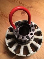
7 turns on first layer, 2 on the second on the trial wire. I can really understand the term "battle of the bulge" :D
image.jpeg
Those modified pliars will be needed, wire is stiff!

3 more turns and the original wire turns and fill ratio is already exceeded!
I consider this test a thumbs up on this wire. Time to order!
 
Wow that looks good! If you can do that as a first time motor winder, you are probably good at working with your hands and the wire actually being somewhat manageable.

1kg wire is 38meters, do you think that will be enough? It sounds like a lot. Removed windings are 420g copper +epoxy with 22% fillfactor... What fill % do you aim at now with the latest findings?
I am tempted to buy wire as well.
 
I think the chaos will start at layer 3 and 4 so i will hardly get 24 turns but i am still calculating length from that.
Estimated fill is 46% (20 turns) - 56% (24 turns), it's tough to meet the 65% that i aimed for.

Length per tooth:
24*(45*2+3.14*(10+2*1.35))+200=3317mm (with 200mm margin)
Where 45=stator length and 10=tooth width and average diameter is at 2nd layer.

Full winding length:
12*3317=39805

I will buy 2 kg as i have 2 motors and think that i will have issues with shorts or mess-ups.
1kg will be too little, no room for errors, at least 1.5kg for a first attempt would be my assumption.

I will sand the stator end coating down to a minimum and then coat the ends again myself with JB weld.
Even after 30 minutes of sanding there's still too thick material left that is closing the slots. Almost everything about this motor is less than optimal in some way.
 
Subsribed. That is awsone handywork.

I hope you get a useful motor in the end. This is surely no good PR for Revolt. Revolt needs to tighten up their overall quality several notches. And if they ever manage to make motors that is actual worth buying for e-bike use revolt needs to be rigid, borderline OCD on the quality control to ensure all customer gets proper products.

Hm someone should make a winding robot to get consistent and high quality copper fill :lol:
 
I need some help with the cables: the hall sensors and temp sensor in one cable will require a 6-pole high temp cable that is max 5mm in diameter or 1/5".

I don't find anything within that range, even 5poles high temp cables i can find (for halls only) are all too large.

Does anyone have a good source?
 
All the parts are now ordered:
3kg 2.5x1.25 copper wire http://www.wires.co.uk (hoping for a really high fill factor) :lol:
8 pcs ss411a halls (i will mount double hall setups+2 to break)
Sensor cable: https://m.elfa.se/sv/styrkabel-05-mm-skaermad-koppar-mangtradig-blank-svart-kabeltronik-sensocord-slimline-105-8x0-05qmm/p/30057029?q=300-57-029&page=1&origPos=1&origPageSize=50&simi=97.5
SKF 6002rs bearings (since i busted one when trying to push out axle the wrong way)
Enamel: http://www.brocott.co.uk/electrical-varnish/

Parts should be here in 7-10 days.
 
Nice job. One way I found to wire stators was to grip the wire with my bench vice, then I could use both hands to hold the stator and wind. I could give a good pull on the wire by pulling the whole stator.
 
I am losing the coasting speed waiting for the wire and other stuff. :pancake:
I'll book next sunday for the rewind so i can concentrate. Until then some other things to be done:

Mill slots for hall sensors
Cleanup and dip stator edges in jb weld epoxy
Remove large bearing
Replace busted bearings
Smooth the slot openings so wire can pass without nicks
Clean and paint rotor&magnets (there was corrosion on two magnets, so much for surface treatment..must be stopped)
 
larsb said:
I am losing the coasting speed waiting for the wire and other stuff. :pancake:
I'll book next sunday for the rewind so i can concentrate. Until then some other things to be done:

Mill slots for hall sensors
Cleanup and dip stator edges in jb weld epoxy
Remove large bearing
Replace busted bearings
Smooth the slot openings so wire can pass without nicks
Clean and paint rotor&magnets (there was corrosion on two magnets, so much for surface treatment..must be stopped)

I would appreciate if you would take pictures and describe your work with the stator prep as well. That would give me input on how to do it.
I have limited experience with preparing stators and I have often ended up with too weak insulation layers that have resulted in shorts.
Maybe it is more straight forward with larger motors like this, when it is easier to afford some extra insulation without taking too much of usable slot space.
 
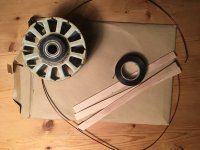
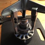
Removed large bearing today, no problems when using a bearing puller.
image.jpeg
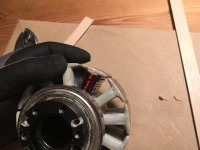
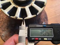
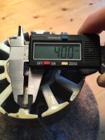
I continued with removing old stator coating. Some drops were almost 2mm high, poking into the slot area. As the smallest slot sets the possible wire area that is really bad.
image.jpeg
image.jpeg
image.jpeg
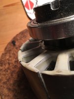
I decided to place the halls against the rear slot edge, that means they all will have a good reference for the position that is 0.5 mm forward of the slot middle.
image.jpeg
image.jpeg
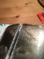
View attachment 1
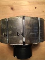
(Look at the uneven coating at the bottom edge, what a poor job!)
I am not happy with the hall slot i made, result is such a crude hack.. I am also a bit concerned that the laminations will get small shorts caused by the grinding so that eddy current losses will be larger.

The offset hall placement will result in a phase angle advance:

Stator circumference = 112*pi = 352mm
That is off course 360 mech degrees
Electrical revolutions per mech revolution= 7 (since 7 pole pairs)

360 deg elec = 352/7 mm --> 1mm equals 7.2 degrees phase shift.
That means i will get a phase advance angle of 3.6 degrees since halls are set 0.5mm forward from neutral position.

It is easy to see that hall placement is critical for the performance, more so for the placement in between the sensors than if all of them are advanced by the same degree (if it's not too much, I think burties´ hall board testing showed small impact up to 20 something degrees). The lag in the controller will anyway delay the phase switching some degrees under higher RPM so the 3.6 degrees will maybe even be too little to be optimal at full RPM. That should be possible to calculate.. I wonder if the high end controllers do this and compensate for that?
 
larsb said:
I am not happy with the hall slot i made, result is such a crude hack.. I am also a bit concerned that the laminations will get small shorts caused by the grinding so that eddy current losses will be larger.
Would shorts on top of the lams really have an influence on the losses?
I mean, isn't the stator anyway only a few mOhm in entire resistance (it is pressed onto an aluminium holder which anyway shorts out all the lams).
Once i grinded the stator of mxus motor beacause it had some rusty spots, but i never thought of that thats why i wonder.

polishing the surface, and pick up all the iron dust with a strong magnet afterwards should help against shorts.
what do you think?

The lag in the controller will anyway delay the phase switching some degrees under higher RPM so the 3.6 degrees will maybe even be too little to be optimal at full RPM. That should be possible to calculate.. I wonder if the high end controllers do this and compensate for that?

yes, modern FOC controllers will compensate the hall delay if the RPM goes up (on adaptto controllers for instance this is called "IND timing").
I always calculate battery volts x kV and compare it with the measured RPM (or speed). Count off 7% when using sine wave controllers because of the lower RMS voltage.
If the values match, than everything should be fine with the timing.
 
My understanding is that the laminations should definitely not be shorted in between them or to any other components in order to reduce the stator losses, the strategy is to create a high resistance in the path for the eddy currents that stops/hinders them.
The stator laminations on my motor is glued to the carrier (could be done in other ways)

My concern is that the isolation between the lams is damaged from the grinding since material from one lam is smeared onto the next one when you grind a slot like i did. Therefore short-circuits between the lams are created - but i don't know how large the effects will be.
 
Could you possible use optical hall sensors/encoders? Thin pancake sized, maybe something like this? http://www.optical-encoders.eu/pancake-encoders.html
These goes on the axle and are supposed to give absolute position.

img3.gif
 
@macribs: i have already bought an RMC22 commutation encoder from here: http://www.rls.si/rmc22-commutation-and-incremental-encoder
If all else fails or i get some time off then i will try it on this setup.

Here's a reference to the thread on Burties' hall timing adjustment board: https://endless-sphere.com/forums/viewtopic.php?f=2&t=19054&start=150

In the graphs it is shown how the no-load amps relate to phase advance for an MXUS motor. Having viewed it again i realize that the effect in losses between the tried hall sensor angles are not actually that small; even if a change from 1A to 1,45A is not large it's still 45% higher.. but that's from a 20 degree advance.

I also wonder why the Revolt motor is best at -24 degrees both for me and Wheazel when used with adaptto controller - that equals an offset hall placement of 3.3mm which is not the case in my motor.

Maybe the original deep hall placement blocks the flux from switching the sensor at the correct time. If the halls are just not good in the neutral position then i won't get a big difference from relocating them to the top surface.

I will have to drill an extra hole for the cable to the 2nd set of hall sensors and place these in different slots. My stator will look like swiss cheese when i am done :)
 
come to think of it: i might just put one set of halls slightly ahead of the other at something like 3mm / 21,6 degrees advance
that way i will have a possibility to choose between at least two positions to be able to see the difference.
 
Looking good larsb.

It's fun to watch your progress.

I noticed you were chasing down a timing board. I commend you on your ambitions to acheive good horsepower from this motor. Can't wait to see what continious power you get.

Thought I might throw out there if you want some help around controlling this thing when it comes time for that, try send Toolman2 a PM. He is an authority on getting motors like this super dialed in and is very helpful to talk to.

D
 
Back
Top