
TheMarkWhite
1 µW
- Joined
- Feb 17, 2017
- Messages
- 3
Good afternoon,
I have been scouring the net for hours trying to piece together and determine how to build my battery pack/bank. This isn't for an EV but this is the only place I've found with a forum that seems promising.
I am building a bluetooth speaker which can accept a power supply up to 25v. I want this to be portable and wireless so I can take it where ever, which is why I wan't a battery bank and not hardwired to an outlet.
I have 17 ICR18650 batteries in good condition and want to make a chargeable battery bank to power the Bluetooth amplifier https://www.amazon.com/gp/product/B01BTJZFY6/ref=oh_aui_detailpage_o00_s00?ie=UTF8&psc=1.
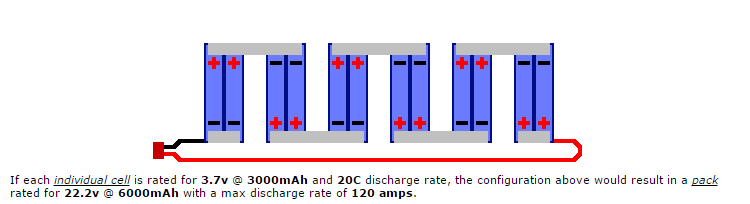
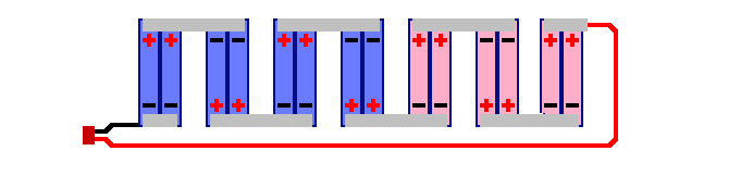
I have 8 Samsung ICR18659 26F and 9 Samsung ICR18650 30A batteries. I believe using these in a 7S2P configuration will get me where I need to be. I'd like to get as close to 25V as possible while having a high mAh. I've also found this PCB which looks to be what I need.https://www.amazon.com/Balancing-Li...-32&keywords=Battery+Protection+BMS+PCB+Board. I've also found this one that could be a possibility http://www.ebay.com/itm/7S-Li-ion-L...Board-PCB-25-2V-25-9V-29-4V-BMS-/321128915784.
Now the question is how do I put all this together? I would assume I should use 8 30A and 6 26F batteries to make each cell the same and not 9 30A and 5 26F. Or does that matter? And how would I connect the batteries to the PCB?
Lastly, is there a way to connect another circuit board or something that would allow me to use standard power adapter to charge this pack? So many questions. I apologize ahead of time for not being super knowledgeable about this but this is why I'm here. I don't want to burn my house down!
Please help! Thank you in advance.
I have been scouring the net for hours trying to piece together and determine how to build my battery pack/bank. This isn't for an EV but this is the only place I've found with a forum that seems promising.
I am building a bluetooth speaker which can accept a power supply up to 25v. I want this to be portable and wireless so I can take it where ever, which is why I wan't a battery bank and not hardwired to an outlet.
I have 17 ICR18650 batteries in good condition and want to make a chargeable battery bank to power the Bluetooth amplifier https://www.amazon.com/gp/product/B01BTJZFY6/ref=oh_aui_detailpage_o00_s00?ie=UTF8&psc=1.
I have 8 Samsung ICR18659 26F and 9 Samsung ICR18650 30A batteries. I believe using these in a 7S2P configuration will get me where I need to be. I'd like to get as close to 25V as possible while having a high mAh. I've also found this PCB which looks to be what I need.https://www.amazon.com/Balancing-Li...-32&keywords=Battery+Protection+BMS+PCB+Board. I've also found this one that could be a possibility http://www.ebay.com/itm/7S-Li-ion-L...Board-PCB-25-2V-25-9V-29-4V-BMS-/321128915784.
Now the question is how do I put all this together? I would assume I should use 8 30A and 6 26F batteries to make each cell the same and not 9 30A and 5 26F. Or does that matter? And how would I connect the batteries to the PCB?
Lastly, is there a way to connect another circuit board or something that would allow me to use standard power adapter to charge this pack? So many questions. I apologize ahead of time for not being super knowledgeable about this but this is why I'm here. I don't want to burn my house down!
Please help! Thank you in advance.
")