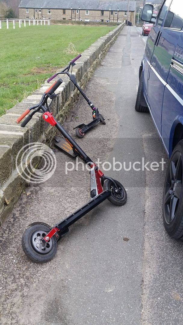
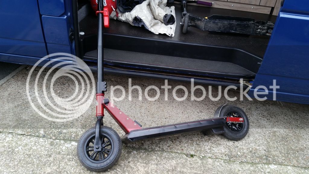
Currie Kick Scooter conversion

beetbocks said:
nice work- im thinking of converting my GT 200 scooter (which looks almost exactly like yours ..) already upgraded the Lead acid to a 7s lipo but kept the original motor and controller
20150720_140009_zpsqxhiujyv.jpg


ill probably use all the electronics off my broken E-scoot so 10s and 6374 motor

20160227_125408_zpsfejjvdni.jpg

20160227_112717_zps65kvm7yf.jpg

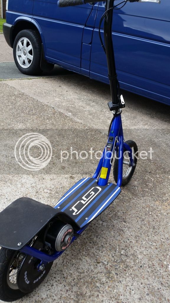
I have one of those blue scooters except mines says schwinn on it and is black. The motor is brushed and not very strong. I think other than color your scooter and my schwinn are the exact same machine. I was going to do this mod to one of the two, but the Currie was the better of the two frame wise and a few other parts. The red and black scooter is an e-scoot? Never heard of it before. Where did you get it? It looks like a nice little scooter. I would be tempted to upgrade it instead. I would be interested in getting one of those. It looks to be well built. I guess it has no brakes.
 
More work done...

The motor plate is basically done except for being painted black. I need to take it off and drill some holes along the front and top so I can attach some aluminum angle for enclosing the front and top around the rear wheel. The front cover will be 1/8" aluminum and the top will probably be a piece of plywood that over hangs the sides and back a little.

I've been working on the other side plate this weekend and finally got it done tonight. I had some 1/8" painted aluminum that worked well for this. It needs to be painted black and drill some holes for attaching the aluminum angle to it.

I used my cardboard pattern to get the axle bolt slot, back bolt hole and to get the overall size down.

side%20plate%201_zpsscjt0knj.jpg

side%20plate%202_zpsc4osny4m.jpg


After I had it bolted in place and drilled a few holes for more 6mm bolts, I then roughed in where the brake caliper would be placed. The large curve is the OD of the brake rotor. The 45 degree line is the angle of the brake pads so they would be perpendicular to the rotor. I roughly drew the shape of the caliper on the aluminum which is the various small curved lines.

side%20plate%203_zpsj9spki3o.jpg


Later I decided a large square hole was a better choice. It makes getting at the brake much easier if it needs work or adjustment. It's not like I need the metal in the plate. Conveniently, the brake caliper is at exactly the right distance from the rotor. It required no adjustment to get it centered over the rotor.

Rear%20brake%201_zpsbspjdqj6.jpg

Rear%20brake%202_zpspslhx8rl.jpg

Rear%20brake%203_zpsq2v8cmr9.jpg


USPS delivered the KART sprocket adapter and the motor sprocket adapter today, but I didn't get them installed. Tomorrow night...and then I can figure out the best chain length and set the tension. Right now I have no idea what sprockets I'm going to use to convert the 3800 motor RPMs into appropriate wheel RPMs. I'm pretty sure whatever I need in sprockets I already have. I have 40, 50, 60, 66 and 72 tooth wheel sprockets and 11 through 18 tooth motor sprockets. I should be good to go.
 
More work done...

The back wheel is done. I need to drill some holes through the motor shaft to secure the sprocket adapter and then the back wheel and drive line is truly done. It took a few strategically placed washers to move the wheel sprocket out a little and the tensioner needed to move in 1/8" and then everything was perfectly aligned. The motor sprocket is on a keyway so it can slide in or out a little. I need to shorten the chain a few links because the chain only engages about half of the motor sprocket. Also, the tensioner extends beyond the front of the side plate a little to get the chain tight. If I move the tensioner in towards the wheel sprocket and shorten the chain a few links, I can get more wrap around the driver sprocket and fix the other minor details. Now that it's all assembled, I should cut off the extra length of the bolts too.

Chain%20line%201_zpsodihssx4.jpg

Chain%20line%202_zpsnadriung.jpg


I also bought better tires. The new tires are a bit taller and wider. The factory tires would have worked, but these ones will handle the speed and power better.

New%20tires_zpskjgziqm0.jpg
 
The back wheel is done done done!!!

These two holes took hours and hours to tap. The shaft to sprocket adapter is stainless steel so it's pretty hard stuff to tap and then there is the shaft which I was barely able to drill with HSS drill bits. Tapping the 10-32 holes all the way through was slow and arduous at best. Most of the time I got less than 1/16th of a turn before I had to back out and try again. If I turned any harder, I risked snapping the tap off in the hole or just binding it up in the new threads. Several times the tap did bind in the shaft, but I was able to break it loose and keep at slooooowly cutting threads. There was some really hard metal in the back hole. That one took probably 5 hours to tap through. I did it last night while watching lots of TV. The shaft end hole was much easier, but still took 2 hours to get through the shaft. What a royal pain! Oh well they are done now and that adapter to shaft is going to be super solid. Next time, I'll use some hardened steel rod and just drill holes through of the same size. Driving the steel rod through will be easy and can't come out since it will be trapped. It will work equally well and will take waaaaaaaaay less time to implement. I taped up the entire motor to keep any metal bits from getting inside.

Driver%20adapter%20tapped%20holes_zpsxhhtzdim.jpg

Driver%20adapter%20tapped%20holes%202_zpsslx8un0q.jpg


The stainless set screws pass all the way through the adapter and shaft. They are just a little less than flush with the surface of the adapter.

Driver%20adapter%201_zpsjp0dzoky.jpg


Motor is mounted. The elongated shaft slot is just slightly wider than the motor shaft so I have to mount the motor first and then slide the adapter on from inside the wheel bay. Then screw in the set screws which also have some blue locktite on them. They are completely trapped underneath the driver sprocket so the locktite is kind of redundant.

Driver%20adapter%202_zpsv7ftlyjc.jpg


The key in the keyway.

Driver%20adapter%203_zpsgu2iwcdq.jpg


Driver sprocket added. There's about 1/16" gap between the driver and the motor bracket.

Driver%20sprocket%202_zps02tcayco.jpg


And the final chain line that is perfectly straight. This couldn't have turned out better if I tried. It's got to be my best work ever on a chain line. It's really smooth and straight.

Chain%20line_zpsckkikolu.jpg


Chain line down the driver to the idler.

Driver%20sprocket_zpszxjn9pke.jpg


Motor mounted and the guard.

Motor%20and%20plate_zpstcl6b96q.jpg


Brake side assembly.

Back%20wheel%20brake%20assembly_zpstjsirgwo.jpg
 
I made some more progress tonight. I finally hooked the motor up to a controller tonight and powered it up. The tensioner needs something done different. Just spinning the wheel or motor and it all sounds fine, but run the motor and it makes a good bit of noise. The steel bearing as a tension roller isn't going to work. It's way too noisy. I'll try something else for the tensioner or perhaps do without and just use the motor to tighten the chain. This is the first time that all systems have been hooked up together and tried out as a whole. All the lights work, horn is good and the watt meter is running. I need to connect up the temperature sensor and of course the back lights are not in place yet. This controller is the old version of the Grinfineon so it loses sync at about 30% throttle. I'm working on a better controller option that can really drive this motor at wattage. The newer version of the grinfineon was a bust too. It's going back to Grintech. Anyway, I've found a couple of options that will probably work out well and deliver 3-6000 watts.

Motor%20hooked%20up_zpss0ehmrei.jpg
 
I'm getting a controller made by PowerVelocity. It will be a 12 fet 100 volt controller. His factory 12 fet controllers normally come with IRF4110 fets. I asked him to make me one with AOT290's instead. The 4110 has a 3.7 micro ohm Rds and is good for 370 watts. The AOT290 has 2.5 micro ohm Dsr and 500 watts. Sometimes less is more and sometimes more is more. In the case of the 290...it's both. It will be a little while before I see the controller, but it's programmable via my cell phone, supports FOC and all the other goodies that a decent controller should have. Because of the FET upgrade a 3000 watt controller now becomes a 4000 watt controller that produces less heat.
 
ElectricGod said:
I'm getting a controller made by PowerVelocity. It will be a 12 fet 100 volt controller. His factory 12 fet controllers normally come with IRF4110 fets. I asked him to make me one with AOT290's instead. The 4110 has a 3.7 micro ohm Rds and is good for 370 watts. The AOT290 has 2.5 micro ohm Dsr and 500 watts. Sometimes less is more and sometimes more is more. In the case of the 290...it's both. It will be a little while before I see the controller, but it's programmable via my cell phone, supports FOC and all the other goodies that a decent controller should have. Because of the FET upgrade a 3000 watt controller now becomes a 4000 watt controller that produces less heat.

I like the sound of the controller a lot being Bluetooth programmable on the fly you got some damn cool stuff in that shed of yours, I done a similar thing with the chain tensioner on my old razor I swaped the roller bearing out for a motor sprocket and it was much better, if the chain does not mesh with cogs as designed it wears out super fast so the bearing just wrecks the Chain and sounds like ass doing it too.
 
Ianhill said:
ElectricGod said:
I'm getting a controller made by PowerVelocity. It will be a 12 fet 100 volt controller. His factory 12 fet controllers normally come with IRF4110 fets. I asked him to make me one with AOT290's instead. The 4110 has a 3.7 micro ohm Rds and is good for 370 watts. The AOT290 has 2.5 micro ohm Dsr and 500 watts. Sometimes less is more and sometimes more is more. In the case of the 290...it's both. It will be a little while before I see the controller, but it's programmable via my cell phone, supports FOC and all the other goodies that a decent controller should have. Because of the FET upgrade a 3000 watt controller now becomes a 4000 watt controller that produces less heat.

I like the sound of the controller a lot being Bluetooth programmable on the fly you got some damn cool stuff in that shed of yours, I done a similar thing with the chain tensioner on my old razor I swaped the roller bearing out for a motor sprocket and it was much better, if the chain does not mesh with cogs as designed it wears out super fast so the bearing just wrecks the Chain and sounds like ass doing it too.

Not a bad idea...using a 219 sprocket as the chain tensioner. The chatter of chain on bearing is pretty loud. I have a partly worn out 219 sprocket that will work well for this purpose. A couple of bearings inside the sprocket will keep it turning nicely. 6800 bearings are 19mm OD and 10mm ID which is an exact fit for this purpose.
 
A little work done over the weekend...

I was trying to come up with a clever way to mount a deck over the back wheel. Eventually I bought some 1/8" thick aluminum angle at home depot and screwed it to the side plates. It extends beyond the side plates a good bit so that the deck covers the back wheel completely. Water spraying up your back as you ride really sucks. The solution is to not let it happen. And now I have cargo space to boot. I'll use a piece of plywood and add grip tape to it for the back deck. Who knows... I might just make a battery box back there too if I can't cram enough into the much expanded battery bay. I might just mount the motor controller to it's under side...if it will fit next to the wheel. Wind off the wheel will keep it cool.

Side%20plates_zpsvqn4uivx.jpg
 
More work done...

I purchased several carbide end mills in 4, 5 and 6mm last week. They arrived today. They were holding up the final bit of work to be done on the back wheel. I had originally put the back wheel together with this freewheel thread to KART adapter that I made from a #25 sprocket that originally was on the scooter. It would have worked, but the heavy duty fixed sprocket I bought a while back was a far better solution. The problem is that it's hardened steel and HSS drill bits wont cut it. Hence the purchase of the carbide end mills. Anyway, they worked perfectly for cutting holes in the fixed sprocket. I also ground the teeth off the sprocket so now it's just a round disk with the same 5 hole pattern in it. I should have bought those end mills a long time ago. I'll defintely buy more of them. The 3 end mills cost $60...so you buy what you need only.

This is the completed back wheel with the better freewheel thread adapter made from the fixed sprocket. This isn't quite the final back wheel assembly. Once I put it all together, I discovered that the wheel sprocket no longer lined up with the motor sprocket so I had to move the wheel sprocket to the inside of the KART adapater. That put it 1/4" closer to the tire, but everything still clears and the chain line is very straight again.

Rear%20assembly%20-%20complete%201_zpswyxzdb6l.jpg


And the back wheel assembly all chained up and tested out. The aluminum plate acts kind of like a speaker cone and amplifies the vibrations from the chain and motor. Hopefully that will become quieter once I connect the two side plates together and add a deck over the wheel. With the wheel sprocket set up like this, it's centered right over the freewheel thread adapter. So, all around a better set up than having the wheel sprocket on the other side of the KART adapter. Next will be cutting a piece of 1/8" aluminum to enclose the front of the back wheel assembly and adding a bracket for mounting rear lights to the tail end. I took a link out of the chain and was able to eliminate the tensioner. The motor slots are all that's needed to adjust the chain tension now. Simpler is better.

Rear%20assembly%20-%20complete%202_zpsejnhcbg5.jpg

Rear%20assembly%20-%20complete%203_zpslzcdryst.jpg
 
E-God, that project is coming along nicely! You're going to need a wheelie bar.

Do you have a contact phone number for LightningRods? I've sent them a few messages but no response.

Also, do you have any extra rear sprockets that will fit the 3 bolt Z50 "Trail Monkey" wheel hubs? I'm trying to get my 219 drive system going and I just need a rear sprocket, preferably around 70-80T or so.

Thanks,
 
Have patients with lightning rod. He will respond usually within a week.

Sent from my SM-G925I using Tapatalk
 
E-ScooterDude said:
E-God, that project is coming along nicely! You're going to need a wheelie bar.

Do you have a contact phone number for LightningRods? I've sent them a few messages but no response.

Also, do you have any extra rear sprockets that will fit the 3 bolt Z50 "Trail Monkey" wheel hubs? I'm trying to get my 219 drive system going and I just need a rear sprocket, preferably around 70-80T or so.

Thanks,

You want a 50 tooth wheel sprocket and 15 tooth driver if you are going to run it on a Monkey wheel with a big block. Trust me on this...that's what I am running and it's a perfect match-up. You want right at 3.33:1 on a 62kv motor. It will get you excellent acceleration and at 82 volts a top speed of 50mph. The largest 219 driver is 18 tooth so feel free to go that size and maintain the 3.33:1 ratio. I went a little smaller so that I had some growth room if I needed it. For a short time I tried a 16 tooth driver sprocket or 3.1:1, but I lost too much acceleration and got just a couple more MPH top speed so I went back to 3.33:1.

Give him some time. him and I keep in touch pretty regularly...usually several emails a week and I haven't heard from him in quite a few days. Something is likely going on to keep him out of touch.
 
Thanks ElectricGod and DVentu,

My last request was weeks ago so I decided to get what I could right from the site instead of ordering the whole package with the custom sprocket.

Since then I've bought a couple things now and added information in the order comments that I need a wheel sprocket but no response. He (or someone) was updating me on order status but that's about it.

I'll try another question from my account messages section so he knows I'm a current customer. I really do need that sprocket soon and the only source I've found for those monkey sprockets for 219 chain is him.
 
E-ScooterDude said:
Thanks ElectricGod and DVentu,

My last request was weeks ago so I decided to get what I could right from the site instead of ordering the whole package with the custom sprocket.

Since then I've bought a couple things now and added information in the order comments that I need a wheel sprocket but no response. He (or someone) was updating me on order status but that's about it.

I'll try another question from my account messages section so he knows I'm a current customer. I really do need that sprocket soon and the only source I've found for those monkey sprockets for 219 chain is him.

I gave him the design and he has to get them laser cut...so yeah they don't exist any place else. They are worth the wait. The steel used is the best stuff. It's really hard. You can't drill it with HSS drills. I'm waiting on a couple of sprockets from him too with the same bolt pattern. You have to be patient. It all depends on the order time frame and if he has other work to give to the laser cutter. Let me talk to him, maybe I can get another one cut. I'm getting a sprocket with that 3 hole pattern and a KART adapter with it. The adapter wont let you go smaller than 60 tooth on the sprocket and you really need a 50T for a monkey wheel.

I just emailed him...we'll see what happens.
 
Thanks EG

He did respond yesterday and I gave him the info. I believe we are on track now.

I appreciate your help.
 
More developments. I took a few days off from work so I had time to get these done.

Yesterday, I made the front plate for the wheel enclosure and the cross pieces for the back deck. It's the same width as the main deck. Everything was fitted, drilled, whatever yesterday and got painted last night and assembled today. The screws are all 1/2" by 10-32, button head. I put some locktite on the threads so they ought to stay put. The wheel enclosure is pretty stiff with these parts added. The back deck got started yesterday, partly cut to size and then finished today. Right now the first coat of paint is drying. Once it's painted the first time around, I'll fit it to the cross pieces, drill bolt holes and repaint it again. Perspective makes the deck look much longer than the back wheel, but really it stops just 1" longer than the wheel. I noticed a mistake I made. The front corners on the deck are cut off at 45 degrees. The front cross piece is too wide with the corners cut off. I'll have to recut it to match the deck profile.

Back%20deck%20assembly%201_zpsnzmyn4mb.jpg

Back%20deck%20assembly%202_zpsb8a8ftsr.jpg

Back%20deck%20assembly%203_zpsfw5dsbyh.jpg
 
Can't stand not posting pics...LOL...this is the whole ride as it exists right now. I have better front forks coming that will take a disk brake and are a little wider so the front wheel isn't attached ATM.

Scooter%2024022017%201_zpsgroxa4hc.jpg

Scooter%2024022017%202_zpsmcyejwgo.jpg

Scooter%2024022017%203_zpssbks5jr8.jpg

Scooter%2024022017%204_zps16qdshrh.jpg

Scooter%2024022017%205_zpscxwa7ooa.jpg

Scooter%2024022017%206_zpsmj5a4s4f.jpg

Scooter%2024022017%207_zpsnbkxrcdh.jpg


It's come a long way from this $80 non functional EV. Geez what a lousy picture too!

IMG_20160930_004130_zpsvueqatrh.jpg
 
More work done...

The back deck is essentially finished now. All the lights are tested and of course the motor runs. I used a 6 pin IP67 connector to connect the rear lights. I'll add grip tape later to it once it arrives.

Back%20deck_zpsecdymdu1.jpg


Brake lights
Rear%20Lights%202_zpstiwy3vem.jpg


Right directional
Rear%20Lights%201_zpsono5fjyt.jpg
 
Amazing! You will definitely be seen with those lights.

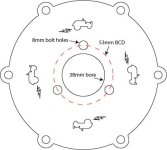
Hey EG: I've heard from LightningRods and they sent me these dimensions for the adapter. He's going to use these for the 50T sprocket I've asked for. I just wanted to make sure these are the dimensions you used for your order for the monkey sprockets.

Adapter Plate dims.jpg

Thanks,
 
E-ScooterDude said:
Amazing! You will definitely be seen with those lights.

Hey EG: I've heard from LightningRods and they sent me these dimensions for the adapter. He's going to use these for the 50T sprocket I've asked for. I just wanted to make sure these are the dimensions you used for your order for the monkey sprockets.


Thanks,

I don't know the diameter of the circle that the 3 bolt hole centers are on, but they are 46mm apart. LR contacted me too. He wanted to confirm the correct part.
 
Thanks EG, but we were looking for the sprocket side, that looks like the disk side.

I don't have the hubs yet, so we were hoping you could do a quick measure of the axle center to bolt center and the bore size.

Thanks again,
 
My apologies EG, that side does appear to be the sprocket side. We were still needing those other dimensions however.

Not having the hubs is a pain when you are trying to order the sprockets.
 
Back
Top