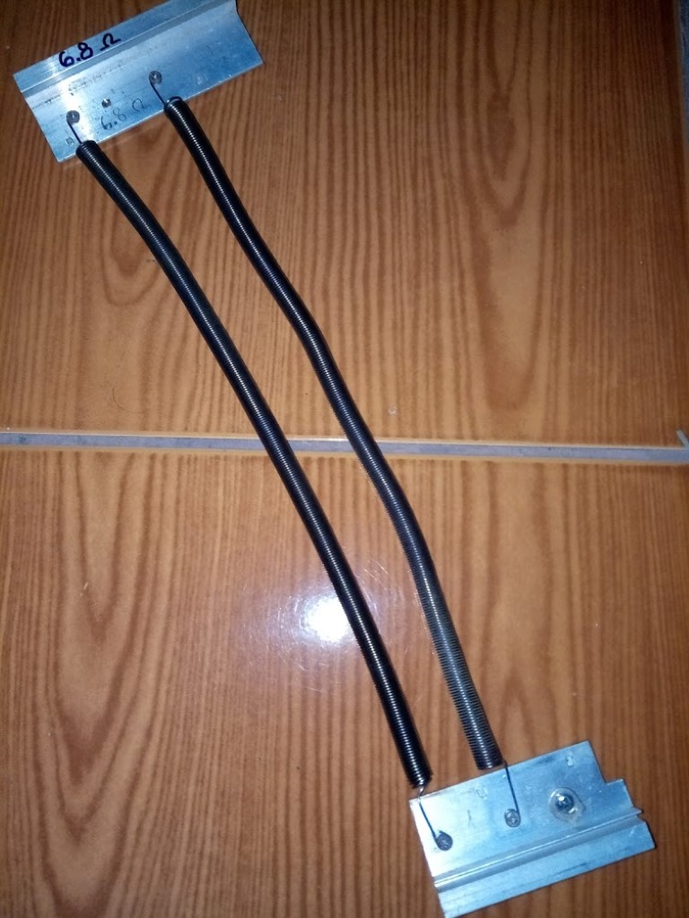
Help needed building dummy load device

Can I give this bulb more than 24v? or should I work in 24v increments in series?
Can I add a simple pot to adjust the amp draw without affecting the voltage?

btw, was always wondering why can't I power a 220v bulb with let's say 50v dc...
The wire inside the bulb looks so thin, how can it not get hot?
 
A potentiometer is for attenuating signal current, not power. You would need a rheostat for what you're doing-- a big one. Not cheap, not plentiful.
 
Chalo said:
...... The advantage of using bulbs with higher voltage, like 120V, is that you can wire all of them in parallel. Then it's only a matter of screwing in or unscrewing them until you have the total resistance/power you want.
...and the disadvantage of using high voltage bulbs is that they have high resistance also.
So if you want to discharge a 48v pack at a reasonable load (20+ amps), you need a whole bunch in parallel to bring the current up.
For example , using a 100W , 120v bulb. To discharge a 48v pack would draw 0.3 amps.
So in order to draw 20amps would need 60+ bulbs in parallel . :shock:
Dont mess with switches or reostats etc, just assemble a "cluster" of bulbs to suit the voltage and current draw you want.
Make other clusters for different voltages etc....KISS !
 
Hillhater said:
I use a collection of 100W , 24v minature halogen bulbs ....(thats ~6 ohm each)
Very handy at our voltage/current levels, and compact too.
bought 10 for $5 off Ebay
Like these ...but much cheaper !
http://www.ebay.com.au/itm/PLATINUM-64638-100W-24V-HALOGEN-BULB-/141901613905?hash=item2109fecb51:g:Q8UAAOSwWTRWvR9X

exactly. 12v or 24v 100w bulbs are fine. the only problem i see with mine, is that you can't solder to them.
you could also buy a bunch of those https://www.aliexpress.com/item/RX24-100W-1K-1R-2R-6R-8R-10R-4R-30R-100R-100Watt-Power-Metal-Shell-Wirewound/32625017497.html?ws_ab_test=searchweb0_0,searchweb201602_4_10000606_10000560_10000073_10000561_10000357_10000074_10000608_10000175_10000507_10000401_10000505_10000558_10000068_10000552_10000063_10000367_10099_10000156_10096_10000569_10000097_10000094_10000090_10000091_10000147_10000144_10000150_10084_10083_10080_10000153_10082_10081_10110_10111_10112_10113_10000535_10114_10000534_10000089_10000086_10000083_10000349_10000135_10000080_10078_10079_10073_10000140_10070_10122_10123_10126_10124_10000546_10065_10068_10000132_10000033_10000030_10000126_10000026_10000129_10000023_10000123_432_10060_10062_10056_10055_10054_10000632_302_10059_10000120_10000020_10000013_10000117_10103_10102_10000016_10000114_10000111_10052_10053_10050_10107_10051_10106_10000621_10000384_10000629_10000101_10000100_10000576_10000579_10000104_10000045_10000578_10000375_10000108_10000377_10000612_10000390_10000613_10000042_10000592_10000594_10000039_10000587_10000036_10000389_10000187,searchweb201603_3,afswitch_1,ppcSwitch_5,single_sort_0_default&btsid=88948207-c685-4570-8988-e44bf7de7d6d&algo_expid=e6be7b06-013b-4525-b2b4-ce2ac0557483-1&algo_pvid=e6be7b06-013b-4525-b2b4-ce2ac0557483
 
rg12 said:
btw, if I connect an 84v battery for discharge on a 1000w resistor, while the voltage is dropping (not due to sag but due to capacity depleting), will the amps be raised automatically in order to stay at a 1000w or will it drop below 1000w? I mean, are the amps constant?
if you ask ohm's law you'll get the answer. the current will NOT stay the same, neither will the power.
but on the other hand: why does it need to stay the same? for internal resistance measurement it doesn't matter as the current is more or less constant over a 10s measurement period, and for discharging it doesn't matter either - you will use your inline wattmeter to read the Ah,Wh etc ...
 
cOiSd38.jpg


nichrome heater element wire. 1400 celcius melting point 8)

add more in parallel if you want higher power
 
Those 100w wirewound alloy resistors can be found on ebay for $1.5, the link here was for $16...

The heater thing has fire hazard written all over it...

I guess I will go with about 20pcs 100w resistors on a heatsink with fans in hope that they won't melt my table...
 
I used an old hair dryer. Most of them have a DC motor to run the fan and they work fine on DC. Just don't use the power switch, leave it on all the time and use the plug to turn it on/off. The switch can arc and fail. Use a CA or cheap chinese amp-hour meter to monitor the discharge.
 
Has anyone looked at using a standard motor controller to regulate the resistive load?

My thinking is that you could use resistive elements to connect the phase wires in a Delta configuration. The Motor controller would send modulated pulses to the load element. A standard 5v throttle could be used to precisely regulate the controller to provide a desired current and/or power load.

I don't think this would quite work out of the box. The hall sensors would not be connected to anything so the controller would think the motor is sitting still.
Does anyone have any thoughts on how to bypass the hall sensors?

fwb
 
funwithbikes said:
Has anyone looked at using a standard motor controller to regulate the resistive load?

A cheap brushed DC motor controller would do it without modification. Such a controller uses PWM to lower the effective voltage to the load. As long as the resistive load was big enough, with low enough resistance, to consume the desired maximum amount of power at the minimum applicable battery voltage, adding a brushed motor controller would be a workable way to dial up any amount of load less than that.

A lot of brushed DC controllers use a 0-5k pot throttle, which can be substituted with a plain dial pot.

Cheap and easy as this solution is, it's not as cheap or simple as as using light bulbs, heating elements, wire wound resistors, etc. in configurable parallel banks. But it would be more convenient when switching testing voltage or changing load levels.
 
I recently installed APP’s on AC power strip and then plug whatever AC heaters, clothes irons, toaster ovens, etc. into the power strip. Connect that “load” to power meter and on to battery pack.

50VDC delivers roughly 1/4-1/3 rated AC Wattage. So a 1500W 120VAC space heater will pull about 300-500W from a 50V battery pack. Another 1500W AC heater will double that and so on, so forth… Easy to parallel to reach desired loads using the power strip.
 
Ykick said:
I recently installed APP’s on AC power strip and then plug whatever AC heaters, clothes irons, toaster ovens, etc. into the power strip. Connect that “load” to power meter and on to battery pack.

50VDC delivers roughly 1/4-1/3 rated AC Wattage. So a 1500W 120VAC space heater will pull about 300-500W from a 50V battery pack. Another 1500W AC heater will double that and so on, so forth… Easy to parallel to reach desired loads using the power strip.

The thing to keep in mind is the current (amps) rating of the cord on the power strip. Most I've seen are rated for maybe 20A max. Anything above that and the cable will get really HOT, and possibly melt the insulation.
 
Overclocker said:
zy8BqA0.jpg


red hot nichrome is so nice to look at. but of course not for clumsy people

LOL I was just going to post that as well. Nichrome wire from Fast Tech would work grrrrrrrrrreat, because its used in vaporizors.
 
Chalo said:
funwithbikes said:
Has anyone looked at using a standard motor controller to regulate the resistive load?

A cheap brushed DC motor controller would do it without modification. Such a controller uses PWM to lower the effective voltage to the load. As long as the resistive load was big enough, with low enough resistance, to consume the desired maximum amount of power at the minimum applicable battery voltage, adding a brushed motor controller would be a workable way to dial up any amount of load less than that.

A lot of brushed DC controllers use a 0-5k pot throttle, which can be substituted with a plain dial pot.

Cheap and easy as this solution is, it's not as cheap or simple as as using light bulbs, heating elements, wire wound resistors, etc. in configurable parallel banks. But it would be more convenient when switching testing voltage or changing load levels.

I thought that it will be a problem controlling just the amps since the pot (so i was told) on a dc controller is controlling the voltage and not the amps.
 
Got an idea for ya, using the Chromium wire, you could buy a bunch coil it up really compactly and tap into coil at different spots. Only issue I could see is maybe by coiling it up, the wire would touch and cause a short, but maybe the wire has high heat insulation on it, like brushless dc motor windings. If you build it properly, you could tap into it just like a Variac/AutoTransformer does.
 
rg12 said:
I thought that it will be a problem controlling just the amps since the pot (so i was told) on a dc controller is controlling the voltage and not the amps.

Since the load is a resistor, the voltage will determine the current, up to the current limit of the controller. As a plus, get a controller you can set the LVC where you want it and it cut off the load when the battery reaches that voltage. You could also tweak the shunt to get the current limit lower and it could automatically keep the current constant during discharge.
 
markz said:
Got an idea for ya, using the Chromium wire, you could buy a bunch coil it up really compactly and tap into coil at different spots. Only issue I could see is maybe by coiling it up, the wire would touch and cause a short, but maybe the wire has high heat insulation on it, like brushless dc motor windings. If you build it properly, you could tap into it just like a Variac/AutoTransformer does.


yep that's what i do. i screw a cable into a 2" piece of 0.3mm nickel. then i jam the nickel into any point along the nichrome coils to get variable resistance
 
rg12 said:
Chalo said:
A cheap brushed DC motor controller would do it without modification. Such a controller uses PWM to lower the effective voltage to the load.

I thought that it will be a problem controlling just the amps since the pot (so i was told) on a dc controller is controlling the voltage and not the amps.

If the resistance doesn't change, the current at a given voltage won't change. The resistance can change as the resistor hearts up, and the voltage can change as the battery drains. But these issues also apply if you use a plain resistor without PWM.
 
fechter said:
rg12 said:
I thought that it will be a problem controlling just the amps since the pot (so i was told) on a dc controller is controlling the voltage and not the amps.

Since the load is a resistor, the voltage will determine the current, up to the current limit of the controller. As a plus, get a controller you can set the LVC where you want it and it cut off the load when the battery reaches that voltage. You could also tweak the shunt to get the current limit lower and it could automatically keep the current constant during discharge.

This is speculative, but since the controller is measuring the voltage drop across the shunt, it might be possible to bypass the shunt with a variable resistor to allow the user to set whatever current limit they wish?

There again, if looking to do that perhaps the best way is to use a common CCCV dc-dc converter where you can dial in voltage and current and connect the output to a resistive load. The advantage there is with an 80V boost converter you could use 110VAC loads and run them near(ish) to their rated load, even if you only have a 12V battery.
 
Punx0r said:
This is speculative, but since the controller is measuring the voltage drop across the shunt, it might be possible to bypass the shunt with a variable resistor to allow the user to set whatever current limit they wish?

Making a variable shunt is difficult, but it is easy to put a potentiometer between the shunt and the current sensing amplifier. Another option would be multiple fixed shunts and a switch.
 
Replacing the shunt with a pot/VR is what I was thinking of, good to know it ought to work at least in theory :)
 
Back
Top