You are using an out of date browser. It may not display this or other websites correctly.
You should upgrade or use an alternative browser.
You should upgrade or use an alternative browser.
18650 cells with tags
- Thread starter Waynemarlow
- Start date
Waynemarlow
10 kW
For those without spot welders and if you only want to build the occasional pack , the tags are the way to go. Once you understand the basics of how you can either shorten or manipulate the tag to suit what ever configuration, the actual soldering is a doddle. However I did struggle to begin with to get the solder to flow along the tag until I had a bit of revelation. The cored ( flux ) solder wire you would normally use does not have enough flux in it to clean the tags correctly and I simply was making a real hash of things and getting frustrated with the slowness. I tried sanding the tags and cleaning with a preparation fluid we had here for cleaning PCB boards' but without real success until I tried a " plumbers " copper pipe flux available from any hardware shop. Magic stuff and works a treat, simply dip your solder wire into the flux ( you don't need too much ) and then heat with a fairly chunky soldering iron. Do use the trick of melting a pool of solder onto the tip and then using that to heat the tag, not trying to use the iron tip directly onto the tag.
I did find one thing out though and please do be aware, do use the cardboard battery protector caps under the positive end. Heat from the iron will melt the shrink wrap around the cell and allow the +ve tag to bridge directly to the outer part of the battery which is linked to the -ve pole. It does make a large short which immediately fuses the tag and leaves a nice hole in it. Exciting at the time.
For the occasional builder, I can only recommend to buy the battery with tags.
Matador
100 kW
- Joined
- Jun 29, 2016
- Messages
- 1,045
Jestronix said:Tabbed cells are awesome, I built a 32s 3p pack out 80v tool packs and the tabs made soldering a breeze. I simply folded the tabs down and soldered without too much worry about the heat going into the cells. All 96 cells have held up well
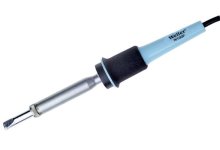
I was thinking of sliding copper bussbars (1.7mm thick x 9 mm wide) into folded tabs of cells. Then solderind tabs with a bit of flux. Got a this Weller WP100 100W Stain glass soldering iron.
What do you think of my design approach ? Wont overheat cells too much ? This is a first try with only two cells (of course there will be 10 cells per holders, using 14 holders.... I'll be making a 14S10P)
View attachment 2
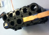
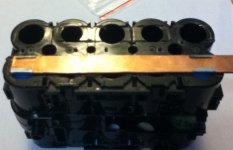
I'm using sony VT4 cells from Makita Packs.
The weller WP100 has a fat tip, bit concerned obout overheating...
Waynemarlow
10 kW
You are probably pushing the need for such heavy buss bars. The mass of the extra thickness and width will indeed need a lot of preheating and will retain heat for a long period of time, everything you don't want to be doing on a battery. Far better to actually calculate the size of cable or bar you need. I was pleasantly surprised just how small the connectors actually need to be. The 14S2P batteries I needed to pull a max of 25A just required 2.5sqm wire. I used 4mm to make sure of voltage loss but we are using very short runs between cells and even that was overkill. There's loads of onsite calculators, do your homework and you will probably be pleasantly surprised on just how small bussbar you need.
Matador
100 kW
- Joined
- Jun 29, 2016
- Messages
- 1,045
Waynemarlow said:You are probably pushing the need for such heavy buss bars. The mass of the extra thickness and width will indeed need a lot of preheating and will retain heat for a long period of time, everything you don't want to be doing on a battery. Far better to actually calculate the size of cable or bar you need. I was pleasantly surprised just how small the connectors actually need to be. The 14S2P batteries I needed to pull a max of 25A just required 2.5sqm wire. I used 4mm to make sure of voltage loss but we are using very short runs between cells and even that was overkill. There's loads of onsite calculators, do your homework and you will probably be pleasantly surprised on just how small bussbar you need.
Thanks for the feedback Waynemarlo.
I must say, I am kind of ambivalent about this too, mainly for fear of overheating the cells.
But in theory, 10 parralleled VTC4 could be able to deliver 300A burst. I'd be happy with just 100A 30sec-burst capability (maybe plan tos hotrod controller in the futur or switch to Adaptto.... For now, I just roll with a 30A BBSHD at 52V).
I thought that the heasink properties of copper would enable not to overheat cells too much.... But I wonder if soldering on those bussbars could be quick enough to avoid damage with my 100W iron. Maybe pre-tinning the bussbar seperatly would help... I just need to solder the legs on top once they are "crimped" tight enough on the bussbars.
Made some calculations : 1.7 x 9 to 10 mm = 15.3 - 17 mm^2. So in cross-section, about equivalent to 5AWG, which is 1.03 milliOhms/meter. BUT, this is flattened copperpipe-made bussbars (15$ per 25 feet). Made out of C12200 alloy, which is only 85% IACS because of phophorus "poisonning" of conductivity of the metal https://alloys.copper.org/alloy/C12200?referrer=facetedsearch.... So I have to derate a bit : R = 1.21 milliOhms/meter.
So assuming flat bussbars behave in a similar manner as round wire, ampacity could be equivalent to somewhere between 5-6AWG, so around 105A (for wiring chassis) or 40A for (power transmission) according to this http://www.powerstream.com/Wire_Size.htm . I'd really like that. Voltage drop and heat generation of energy is somewhat directly related to resistance of the conductor... So the bigger the better (unless it weight a ton!)
BTW, what's the difference between those two rating (chassis wiring versus power transmission) and why is there such a huge difference ?
999zip999
100 TW
If solder you can drill a small hole in the copper and pre tin on under side of copper. Light sanding. Flux a sponge. Be fast with a Hot, clean and tinned tip. After tinned tip can be flash cleaned with wet sponge it will b brighten up.
When you heat the hole with solder and flux it will tranfer the molten solder thru the hole and do a fast joint pull iron and apply damp sponge
When you heat the hole with solder and flux it will tranfer the molten solder thru the hole and do a fast joint pull iron and apply damp sponge
Matador
100 kW
- Joined
- Jun 29, 2016
- Messages
- 1,045
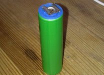
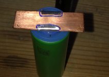
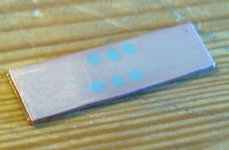
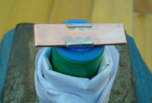
I gave it a try with a dead cell.
Looks good, but I'm going to have to work on my technique.... The 100W iron is just soo fast at melting everything, I think I should use just a a little bit lower power. Maybe 60W or less.
Here's some pics...
 View attachment 6View attachment 5
 View attachment 3
Matador
Looks good, but I'm going to have to work on my technique.... The 100W iron is just soo fast at melting everything, I think I should use just a a little bit lower power. Maybe 60W or less.
Here's some pics...

 View attachment 6View attachment 5
 View attachment 3

Matador
Matador
100 kW
- Joined
- Jun 29, 2016
- Messages
- 1,045
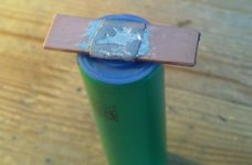
I removed the positive silicon protective ring to examine the solder.
I think the solder is far from the batt content.
Also, you can see that the cells tab leg are solder from top, but not from bottom
See that EMPTY SLIT-LIKE SPACE betwee the copper bussbar and the cell poitive post....
That means the weld is at least 4 millimeter away from battery post....
I dont know how much heat would seep into the cell via the cell tab.
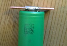

What do you think, is this still a big mistake ? Soldering took about 2-3 seconds (it's my first try!)
Matador
I think the solder is far from the batt content.
Also, you can see that the cells tab leg are solder from top, but not from bottom
See that EMPTY SLIT-LIKE SPACE betwee the copper bussbar and the cell poitive post....
That means the weld is at least 4 millimeter away from battery post....
I dont know how much heat would seep into the cell via the cell tab.


What do you think, is this still a big mistake ? Soldering took about 2-3 seconds (it's my first try!)
Matador
Matador
100 kW
- Joined
- Jun 29, 2016
- Messages
- 1,045
That's what I made the copper bussbar from (25 feet for around 15 USD - Made in Canada) :
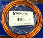
Label says :
GREAT LAKES COPPER INC.
1010 CLARKE RD, LONDON ONTARIO N5Y 5S6, TELEPHONE 1-80-265-9271
GENERAL PURPOSE TUBE
TUBE POUR APPLICATION GÉNÉRALE
065524046033 (codebar)
DIAM. EXT. 1/4" - LENGTH 25'
MADE IN CANADA
ON DATE : 11/27/24, FABRIQUÉ AU CANADA.
From what I can see on Great Lakes Copper Inc website, that general purpose pipe follows the ATSM B75 norm (seamless copper tube). It's made of "Alloy C12200" copper :
Alloy C12200 (https://alloys.copper.org/alloy/C12200?referrer=facetedsearch) :
Chemical composition : min 99.9% copper, but also phosphorous (P), min 0.015%, max 0.040%.
Conductivity : 85 % IACS @ 20°C (Resistivity of 2.02 x 10⁻⁸ Ohm.m)
Before flattening (and sanding) the pipe it was : Outer diameter : 0.25 inch ± 0.03 (6.350 mm), inner diameter 0.19 inch (4.826 mm), wall thickness 0.03 inch ± 0.003 (0.762 mm) mm -->
Conductive cross-sectionnal area: (31.6 - 18.29) = 13.38 mm2 wich is equivalent solid wire diameter of 4.127 mm.
Considerin this copper alloy is 85% rather than 100 %IACS (Resistivity of 2.02 x 10⁻⁸ Ohm.m), This copper pipe is 1.51 milliOhm per meter http://eddy-current.com/conductivity-of-metals-sorted-by-resistivity/
This resistance is very slightly slightly less than a pure copper (100%IACS) 7AWG gauge wire (1.63 milliOhm/meter) which is rated for 90Amps...
Funny thing is that 50 ft of that copper pipe would be 23 milliohm resistance, which is about the DC internal resistance of a brand new VTC4 cell.
It will be should be OK if the copper rests on the positive terminal of the cell - it's a hollow cap, so heat conduction to the cell interior will be poor. It's soldering to the bottom of cells that's the real problem (AFAIK). For soldering tabbed cells here, I put a card sticker (actually the centre pieces from the insulating rings normally put on cell tops) on the cell bottom where the tab was welded, laid the copper bus on the sticker, folded the tab over the top and soldered. That way the card insulates the cell from the soldering heat.
Matador
100 kW
- Joined
- Jun 29, 2016
- Messages
- 1,045
Punx0r said:It will be should be OK if the copper rests on the positive terminal of the cell - it's a hollow cap, so heat conduction to the cell interior will be poor. It's soldering to the bottom of cells that's the real problem (AFAIK). For soldering tabbed cells here, I put a card sticker (actually the centre pieces from the insulating rings normally put on cell tops) on the cell bottom where the tab was welded, laid the copper bus on the sticker, folded the tab over the top and soldered. That way the card insulates the cell from the soldering heat.
Excellent idea... Put the cardboard "puck" in the center of the top, lay the copper bussbar on top, fold the tabs legs over and solder.
The positive hollow cap seems it's no problem to solder, in truth.
I did a test yesterday to appreciate that the positive is no problem (not the best test know, but just to give a gross idea)...
I charged the soldered cell @1.0A and discharged it completely @ 0.5A to measure capacity with my Foxnovo 4S digital charger (4.20 to 2.75 volts). The soldered cells was one of the very DEAD cells in the batch that i scavenged from Makita packs (sitting at 0.03volt when scavenged...). I wasn't even planning to use it, apart from testing the spotwelded tab's robustness but pulling apart the tabs with plyers (I took the negative tab off)... Well I had another cell that was dead, sitting at 0.04 V (both dead cells were originally both sitting dead, in the very same Makita pack, at the same voltage and were both in parrallel with each other (2P). So I figured they should be of a comparable damage/loss of capacity from sitting at the low voltage).
Well upon discharge I got similar discharge capacity for both cell (soldered and unsoldered ) :
Dead cell (#114) with soldered bussbar on positive terminal : 1923 mAh
Other dead cell (#116) but no solder, pulled from the same Makita pack (#116 and #114 were in parallel) : 1928 mAh
Seem comparable to me. But when I tested the other 128 good cells with the exact same charger/parameters, they were, on average 2196 mAh (± 91 mAh, 95% confidence interval ; n = 128).
(Rated 2000 mAh ; typical 2100 mAh @ 0.2C).
I want to try some testing for the negative terminal in the future, as soon as I can find the time to do it.
Was thinking of taking a dead cells, open it with a copperpipe cutter, gut out the internal of the cells.
Then put a thermocouple/temp probe from the inside of cells, right at the negative teminal, put some thermal conductive paste to fasten there, right on the negative post.
Measure temp profiles from the inside while soldering at the same time... I it doesn't go over 50°C, it's golden.... I think the tip of my 100W welder is at least 250°C... so gotta work fast.
999zip999
100 TW
My 80watt weller old style is a monster. Pre tin clean tip and flux. Clean tip with wet sponge or small wire brush. If things are right it goes fast. If not someting missing.
999zip999
100 TW
Matador that looks like it can carry current.
Matador
100 kW
- Joined
- Jun 29, 2016
- Messages
- 1,045
999zip999 said:Matador that looks like it can carry current.
Hopefully
I find that trying to minimise resitance is a challenging task when trying to assemble a pack !
999zip999
100 TW
Resistance is heat.
I suspect that if you are only soldering on top of the copper strip, the copper mass will act as a heat-sink, and very little heat will reach the cell, if any at all. I would have a high level of confidence in any pack made this way.
Back when there were a lot of soldered packs, the big tip was to use a high-watt soldering iron with a fat tip. That way, the iron's contact with the nickel strip could be very short (so the inside of the cell didn't get hot). Even then, the majority of cells worked fine with no heat damage from the soldering. It was only a small percentage of cells that ended up damaged, which pushed builders to look for options. I doubt any cells would ever be damaged with this new method.
Doing it this way doesn't require a spot-welder, so for builders who have some time on their hands...well done, matador.
Matador
100 kW
- Joined
- Jun 29, 2016
- Messages
- 1,045
Thanks.
Just a little test while I'm still opening more Makita Packs and scavenging more VTC4 cells to test...
I'm about halfway in the testings.... Than I'll have to do DCIR load testings.... (Planning to match cell for Capacity, DCIR and manufacture date as much as possible, to make a good equilibrium). Then I'll start the assemble.
I have 290 VTC4 cells minus the bad apples (I think 6 cells in total but need more testing). All are less than 100 cycles.
I want to do 3 battery packs, all three to be used with 30A-(for now)-BBSHD with BestechBMS Power HCX-D131 80A BMS.
1) 14S10P (19.6Ah - 1017Wh usable ; 6.3+ Kg ; 140 cells)
2) 14S6P (11.7Ah - 608 Wh usable ; 3.8+ kg ; 84 cells)
3) 14S4P (7.8 Ah - 404 Wh usable ; 2.5+ kg ; 70 cells)
I made a little range study and calculated estimated real Ah at load for real HVC and LVC of my setup. Also did intrapolation for finding estimated temps of pack to be expected.
See it here in the "Range Study" tab of my excel file : View attachment Makita VTC4 cells from doctorbass.xlsx
Found a small box for the HCX-D131 80A BMS... With a bit of sanding/dremmeling (here's the box http://www.hammondmfg.com/pdf/1599H.pdf ), the BMS fits in.... I'll be connecting all BMS leads with blue andersons PP45 connectors (7 connector wide by 2 connector thick.... all stack togoether, with embedment bushing in the bms box). The charge cable (8 or 10 AWG) will be andersons PP45 (red and black) connectors while discharge cable will be Andersons PP75 -6AWG lugs (fit my 4AWG cable) with pure copper 4AWG welder cable and a hydrolic crimper tool for it).
I will be able to easily swap my BMS from pack to pack with this anderson system. Also able to easily disconnect BMS if I ever need long storage (but this BMS only eats 20 microAmps soo draining the half charged pack would take few decades).
I'll also have to find a way to wire the cellLogs on the pack. I'd also want to put an Normally Closed 100A 48A contactor for the battery (in order to install an antispark switch inside the battery....) But can't find such an NC contactor in the 48V range... they're all NO. When pressed, the switch would drive the contact to OPEN the mains battery leads so current could only flow via an alternative path with a big 5.6 Ohm resistor in it... When the switch is realeased, the contactor CLOSES again and the current follow path of least resistance (the big 4AWG cable to the controller)....
I know, overkill
999zip999
100 TW
Not yet will you have a extra set of sense wire for a cellog style monitor. Unpluging and plugging the bms can cause problems.
Matador
100 kW
- Joined
- Jun 29, 2016
- Messages
- 1,045
Yes, I plan to have an extra set of sense wire for the two CellLogs I'll use. I've already bought three CellLog8M and 6 x 9 pin JST cables. I don't wont to spend more money on PP45 connectors for the cells logs. Andersons can get expensive here.. I will just solder the CellLogs wires with 9 pin JST ( x 2) directly to the battery. When I want to remove the CellLux, I can just pull the JXT plugs... I know CellLog can drain the battery, particullarly the 1S series i think.999zip999 said:Not yet. Will you have a extra set of sense wire for a cellog style monitor ?
Why is that ? Is there anything I should know that escaped my awarness ? (My BMS is a 14S 80A HCX-D131 from BesTech Power)999zip999 said:Unpluging and plugging the bms can cause problems.
Anybody know where I can get a Normally Closed 48V contactor that can take some amps.... All I can find is the Normally opened style ones.
Similar threads
- Replies
- 22
- Views
- 327
- Replies
- 7
- Views
- 156
- Replies
- 3
- Views
- 1,335
- Replies
- 10
- Views
- 202

