Fuse-wire for individual cells, DIY Tesla style

In 18650 Li cells, the +ve end cap is separated from the active cell material by an air gap which will minimise any heat effects when soldering or welding to the external cap.
However, there is a risk of heat damage to the insulator gasket between the end cap and the cell case if excessive heat/ force is applied.
 
Hey I've been trying to figure a proper size to try this and came with an issue : what about added resistance of the fuse wire compared to a "normal sized" one? That's potential lot of voltage drop to account for.
 
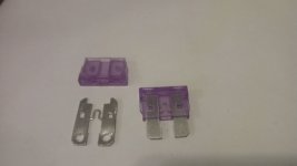
I was curious about the same thing. The commonly-used pure nickel ribbon is 7mm wide and 0.15mm thick. That makes the cross section 7mm X 0.15mm = 1.05mm squared. Pure nickel has a conductivity of 22/100 compared to copper, so 1/4 at best? https://www.bluesea.com/resources/108/Electrical_Conductivity_of_Materials


This means a 1.05mm squared nickel wire would be equal to a copper wire with a cross-section of about 0.27mm squared? That is equal to round cross-section copper wire of___23.5-ga? http://www.engineeringtoolbox.com/awg-wire-gauge-d_731.html

7mm X 0.20mm = 1.4mm sq. So, 1/4 is 0.35mm sq copper, equal to...22-ga round cross-section copper wire

Nickel has a much higher melting temp of 2650F (1450C)...and copper is 1980F (1080C), 25% less? I imagine this is one of the reasons nickel is often used...it can get very hot without melting, but...it also causes a LOT of voltage sag due to resistance. You are converting battery watts into a lot of heat if you are using nickel.

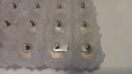
The series-bars can be very fat copper (look at pics of E-motorcycle batteries, they regularly draw 200A+), but the parallel connection only has to normally provide 30% of the individual cells max capability (10A max cell = 30A melting fuse wire?).

If you are using high-amp cells in a very small pack, it would be tricky to get the fuse-wire "just right", but...I think if you have a fairly large battery pack with average-current cells (in order to access higher capacities), its easy to find a diameter of copper wire that will work. As an example, an affordable 3400-mAh GA cell seems to be comfortable at 6A each, and warm at 10A. maybe have the fuse wire melt at 30A to minimize resistance during normal operations? If the pack is a large 7P (14S / 24-Ah), then the full 7P amps would be an unrestricted 70A at a minimum, and likely more.

By comparison, on a tiny 2P pack using a high-amp 25R cell, a fuse-wire on each cell would need to flow 20A in normal operation without getting hot, and for an acceptable level of resistance, maybe 30A before it gets warm? That is close to the 40A the tiny 2P pack would put out. Without the BMS to restrict the amps during a short, a 2P 25R string would put out higher amps than 40A, but...to have a fuse-wire that is only warm at 30A, it might need to melt at 40A-50A.

Either way...if you were an electrical engineer that was hired to design a circuit and you specified pure nickel wire, you'd probably be fired. Tesla uses nickel-plated copper, nickel for corrosion resistance, and 95%+ copper core for conductivity. They use ultrasonic vibration friction-welding instead of spot-welding or soldering. Fuse-wire is easy for them to size for low resistance because they have an enormous parallel groups (high parallel amps) and only draw small amps from each cell.

[I am still learning, so...there's a good chance I've gotten something wrong here. Don't make any big decisions without doing your own research]
 
Vanarian said:
: what about added resistance of the fuse wire compared to a "normal sized" one? That's potential lot of voltage drop to account for.

i doubt voltage drop across a fuse wire link would be significant considering its length is probably only 1/2 inch ..(1cm ) at most.
an on line calculator gives the voltage drop for 0.25mm sqr copper wire carrying 10 amps @ 4 volts, is 1.3 volts per meter
So for that 1 cm link wire the drop would be 0.013v .( 13 mV )
in a 10s pack ( 40v) thats 0.1v total at 10 amps.....OR , 1.0 Watt loss at 400W discharge.
PS.. i think a 0.25mmsqr (0.56mm dia) Cu wire has a fusing current of 30A approx ?
 
It should be fairly easy to set up a test cell with wires or nickel strips, discharge into a load with an ammeter and measure the voltage drop across the wire or strip. We can then calculate the resistance. Once that's known, all kinds of different configurations can be evaluated just by doing the math.

It would also be nice to measure what kind of current those cells can put out into a short. This could be done quickly, with a pulse and possibly not explode the cell.

The fuse link should blow somewhere between the rated current and the short circuit current, probably about half way.
 
fechter said:
It would also be nice to measure what kind of current those cells can put out into a short. This could be done quickly, with a pulse and possibly not explode the cell.
That would obviously depend on which cell you are using...but several of the high output cells have a pulse rating of 100+ amps.
But i agree, even those without high pulse ratings can probably give some interesting amperage if shorted !
 
Hillhater said:
That would obviously depend on which cell you are using...but several of the high output cells have a pulse rating of 100+ amps.
But i agree, even those without high pulse ratings can probably give some interesting amperage if shorted !

It would be nice to get a ballpark figure at least. Some way to record the current would be great. I might be able to do something with a digital oscilloscope and a 100A shunt I have. I have some sacrificial cells I can test with too.
 
Wouldnt the max current for a dead short be proportional to the cell DCIR ?
..and as such it could be calculated theoretically ?
Such that a cell with typically 50mohm IR, might be expected to give 3.8v/0.050 = 76 amps ??
And double that for a cell with 25mohm IR.
Davide Andre has tested and tabulated many cells by their "Shorted discharge time"
IE, the theoretical time a cell would take to discharge if dead shorted..
http://liionbms.com/php/wp_short_discharge_time.php

Also this.....Quite dated results , but interesting data..
https://www.researchgate.net/publication/269707255_External_short_circuit_fault_diagnosis_for_lithium-ion_batteries
 
How about his?
file.php

file.php

file.php
 

Attachments

  • IMG_20170514_104000.resized.jpg
    IMG_20170514_104000.resized.jpg
    41.6 KB · Views: 5,508
  • IMG_20170514_105507.resized.jpg
    IMG_20170514_105507.resized.jpg
    63.7 KB · Views: 5,508
when reading this threat i wondered if it is possible to spot weld copper wire to a cell.

and the anser is Yes
file.php


its a 0.25mm diameter tinned? copper wire, tested to 5 Amps it got hot but didn't melt.

when i tried to pull the wire off it broke at the weld, so that's good.
 

Attachments

  • wire_to_18650.jpg
    wire_to_18650.jpg
    64.1 KB · Views: 5,502
Nice weld.
I think, best fuse material, is:
1)low melting temp and
2)low heat conductivity material
I tried to use cooper in the past, but it pumps heat across pretty fast and thin wire, that rates for 3A can take 30A if there is enough heat storage capacity on the ends, like big cooper lugs or maybe even cell can. I think it is the reason Tesla uses some kind of special Aluminium or Zinc alloy, that has mentioned properties. At least Automotive fuses are usually Tin or Silver plated Zinc alloy.
Does someone know what exact formulation is Tesla fuse?
 
I understand that soldering would be pretty bad for the battery, but just thinking if spotwelding S shaped nickel strip and soldering the fuse wire to it would fix this problem. The main benefit of soldering is replacing the battery in something like the powerwall would be easy. Instead of cutting the nickeld strip cleaning the surface and spot welding new one.
We already solder the bms wires in between the cells.
 

Attachments

  • fuse.jpg
    fuse.jpg
    22.6 KB · Views: 6,896
multifrag said:
I understand that soldering would be pretty bad for the battery, but just thinking if spotwelding S shaped nickel strip and soldering the fuse wire to it would fix this problem. The main benefit of soldering is replacing the battery in something like the powerwall would be easy. Instead of cutting the nickeld strip cleaning the surface and spot welding new one.
We already solder the bms wires in between the cells.

One concern is that BMS wires do not carry any real significant current as opposed to inter-cell connections.
 
cal3thousand said:
multifrag said:
I understand that soldering would be pretty bad for the battery, but just thinking if spotwelding S shaped nickel strip and soldering the fuse wire to it would fix this problem. The main benefit of soldering is replacing the battery in something like the powerwall would be easy. Instead of cutting the nickeld strip cleaning the surface and spot welding new one.
We already solder the bms wires in between the cells.

One concern is that BMS wires do not carry any real significant current as opposed to inter-cell connections.

This was more for a powerwall type of project. For ebike I don't think it would work as we are limited by the space, but when someone wants to make a 40Kw ''powerwall'' the solder would help out troubleshooting a lot. So the question would be if the nickel strip protect/help the battery from heating up to much when soldering the fuse wire.
 
There is the risk, when main current transmission path in mind, red glowing pre blowing cooper fuse could liquefy pretty big chunk of solder and this droop can flow somewhere you do not want it.
 
parabellum said:
There is the risk, when main current transmission path in mind, red glowing pre blowing cooper fuse could liquefy pretty big chunk of solder and this droop can flow somewhere you do not want it.

I do agree about not wanting the blobs of solder getting down the vent of the cell, but I just can't really imagine how a 15w fuse wire can melt solder.
 
multifrag said:
parabellum said:
There is the risk, when main current transmission path in mind, red glowing pre blowing cooper fuse could liquefy pretty big chunk of solder and this droop can flow somewhere you do not want it.

I do agree about not wanting the blobs of solder getting down the vent of the cell, but I just can't really imagine how a 15w fuse wire can melt solder.
I am more about bike pack and 15-50A fuses and use of copper, being the best affordable, static heat conductor. I have personally looked at 1 cm section of red gloving copper, conducting 30A clamped to big copper lugs right and left for a minute and then fusing it in few seconds with 5A grabbed with steel crocks with next to no path for heat to escape. Remember, there are >1000C where copper melts and only ~ 180C for most common solder.
 
FTW!

When I was posted at Tesla the "sewing machine" that performs this activity was in our area. Pure awesome. Everywhere I work I am under NDA and have to bite my tongue on many awesome things... sometimes for years... so thanks for posting it for public consumption.

Individual fusing is a super-win on safety.
The wire can conduct perfectly fine... (there were arguments about this)... no appreciable loss.

I am a fan of self-resetting fuses as well on any BMS balance tap wires. Yes... they vary in resistance... but going into the high impedance of the ADC of the BMS it makes no difference.

I totally get the industries that are shooting for the highest energy density (motorcycle...)
But to make this movement fly we will need batteries to be bullet proof (literally).
Once they are safer than 20 gallons of gas...

-methods
 
One more example. Copper strips as the series busses. Common 7mm X 0.15mm nickel-strip spot-welded on the negative ends for the parallels, Thin/narrow strips as fuses on the positives...spot-welded to the positive nipple. Solder used at every series/parallel crossing, and solder used to connect fuse-strip to the copper series busses. Fast forward to 8:00

https://youtu.be/PiNeL01VD0M?t=483

[youtube]PiNeL01VD0M[/youtube]
 
Big advocate of cell level fusing here!

See my thread below, real world testing of 30Q 14s 4p. I now have 300 km on this pack, going strong, and using recycled cells

https://endless-sphere.com/forums/viewtopic.php?f=14&t=93297

I have used the axial glass fuses, they are generally low amp but they do contain the burnt fuse material and you can see when fuses are blown...if you use clear heat shrink as I do.

I like the idea above using the fuse material from small blade fuses :D Any update on that idea Parabellum?
Very interesting topic this one!
 
Back
Top