KingQueenWong
100 mW
- Joined
- Dec 18, 2016
- Messages
- 39

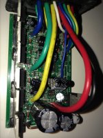
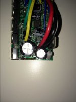
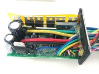
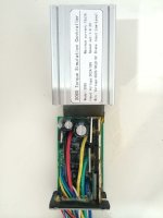
The latest connected wires,but it fail to rotate too. The power supply volatage is adjusted to 24V.
But are you trying to run the original controller, with the original firmware or trying my OpenSource firmware?KingQueenWong said:
The latest connected wires,but it fail to rotate too. The power supply volatage is adjusted to 24V.
Good plan!!KingQueenWong said:I am trying to run the original controller,next i will try your firmware,finally i will change your firmware.
")
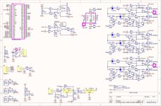
KingQueenWong said:Maybe you are right,i try to hack the controller's schematic.
KingQueenWong said:I am trying to draw the s06s controller's schematic.
even better if was designed with KiCad because is OpenSource.
Thanks. Seems it is ok. I don't know if there is any special flag on configuration bits of STM8S105 that can cause this behavior I did refer...KingQueenWong said:
The NRST pin just connect a 100K pull up Resistor to 5V and a 0.1uf Capacitor t0 GND.
The SWIM pin just connect a 10K pull up Resistor to 5V.
)
Seems that you did finish the schematic, which is great!! Can you please push to github and export to PDF and PNG file??KingQueenWong said:I am trying to draw the s06s controller's schematic.

Thank you for your words. Talking by myself, I would like to give some love to this cheap and widely available EBike motor controller and technology. Even if we don't get a better firmware than original, at least sharing knowledge about them is important for repair and modding/hacking.MisterMint said:Nice to see someone taking care of the cheap stuff from the land of china.