Idiots guide to rewinding Revolt 120 pro

I will switch the motor on my bike to this one (if it runs as it should)

I am limited by the 120A BMS on my battery and the Kelly 300A (theoretical) phase amps so i am not sure if it will be a big difference, might have to get more battery or even controller power. I'll gear to 100km/h and set the amps at max on the controller and do some trials.. if needed i'll build a 20s battery expansion pack with 18650 cells :D
 
Awesome work :)

When assembled, could you characterize the motor by measuring phase to phase resistance as well as no-load amps at two voltage levels?

Preferably on your stock and on the new, then you can accurately state how much you've improved things by :D
 
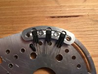
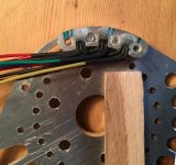
Outside hall sensors and wiring done. I'll skip the inside sensors and just go with these.

Honeywell SS460 sensors were my best guesstimate from reading some data sheets. They are bipolar latching type so each time a magnet moves past the sensor it latches to on or off and stays in that state until a magnet of opposite polarity passes.

I milled a slider earlier for adjusting the halls, glued sensors with CA glue plus baking powder. That's a nice combination, quick, hard and quite strong!
image.jpeg
image.jpeg
Heat shrinked the cables and slider to keep them together - voila!
 
I haven't really figured out what to do with the rewound motor.. If i ride it hard on roads then i will need new brakes, tires and wheels to match the speeds.

Already going 65kph today is pushing it.. Even though the tektro dorado ebrake i use is supposed to match ebikes it cannot stop me from high speeds. If you cant lock wheel or do a stoppie from all speeds then brakes aren't good enough.

Anyway;

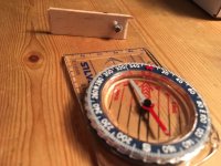
Mounted sensor magnets tonight. I used a compass to find the magnet polarity and make a small magnet direction feeler.
image.jpeg
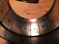
Then i used it to find and mark all the rotor magnets polarity.
image.jpeg
Glued and ready for paint!
 
Me too, when I first read about Revolt I thought it might be the way to 125cc power. Not necessarily to go way faster but to go places where hubs struggle. Like deep loose sand or steep slow technical climbs. Shortcomings of the Revolt was a disappointment for me as well as many others that was showing interest in those light weight motors. Ease of use, like swing arm mount, no extra stage of reduction all got our hope high for Revolt so the fall was too bad.

Iirc the claim was short bursts of 15 kw peak. I really wonder if that is within reach with your revolted Revolt. If it is I am sure others will find this thread and maybe get inspired to do a custom wound themselves for great size motor.
 
larsb said:
I haven't really figured out what to do with the rewound motor.. If i ride it hard on roads then i will need new brakes, tires and wheels to match the speeds.

Already going 65kph today is pushing it.. Even though the tektro dorado ebrake i use is supposed to match ebikes it cannot stop me from high speeds. If you cant lock wheel or do a stoppie from all speeds then brakes aren't good enough.

Just because you can go faster doesn't mean you must. It's definitely a lot more fun getting TO that speed quicker and more efficiently though. Personally I wouldn't change your gearing at all if you're already satisfied with your available speed range (other than correcting for your probably altered motor kv of course). You'll be making more torque from the same amps and have the ability to run many more amps without running into huge losses. That means more fun in my experience :)

Like you mention about brakes - I would say if you're not able to lift the front wheel on command at any desired speed then you don't yet have enough torque. Everything you've done should help with that 'problem' ;)
 
Like you mention about brakes - I would say if you're not able to lift the front wheel on command at any desired speed then you don't yet have enough torque. Everything you've done should help with that 'problem' ;)

That comment :D :D..
It just cracks me up, really summarizes the spirit at ES :D

Alrighty then, i'll skip the thinking part and get on with it :D :D
 
Does your Kelly controller not have regen braking or you free wheeled? I have 203mm front and back that in hindsight was a huge waste of money as they only get used at the stop light...
 
I am freewheeled but kelly has regen if i want it. Doubt it will be nice to use it though since there's always some slack in the chain.

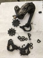
The derailleur on my bike gave up today. Bearings on jockey wheels are worn to the bone after 5000km of riding. I will have to fix the new motor, axle on the one i use does not allow a straight chainline.
image.jpeg
 
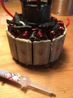
I've fitted a temp sensor, managed to get it between the end turns and stator. A glass fibre/acrylic sleeve protects the cables since i never found any thin high temp wires.

Sensor glued with fast setting epoxy on coil no 10:
image.jpeg
 
Yeah my motor sticks out quite a bit for the perfect chainline... I don't see any derailleur handling the abuse I put through it anyways your work on the revolt is amazing!
 
Trying the compass after using it with the neodym magnets shows it's changed direction.. True north is upwards in the pic!
Don't use your favourite compass for this..

I'd use just the magnets themselves to try for polarity if i did it again.
 
I had plans to do a vacuum infusion with silicone to pot the stator.
I've done infusions with epoxy and carbon fibre before - it's not easy to get it exactly right the first time..

As always justin le beat me to it, his tests of a potted MXUS hub showed small gains:
https://endless-sphere.com/forums/viewtopic.php?p=1116645#p1116645

It is not worth the risks of screwing it up even though an infusion would be better than the full potting Justin did. I'll use normal electrical varnish instead. Bought some black varnish from Brocott/UK, haven't found it anywhere in Sweden:
http://www.brocott.co.uk/electrical-varnish/
 
I cleaned rotor with rubbing alcohol and emery cloth to prepare for painting.
image.jpeg
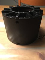
Matte painted rotor:
View attachment 1
Paint didn't want to stick evenly on the side plate so it looks quite coarse, should've removed plate before spraying..
 
Electric varnish applied tonight, quite sticky..
I heated the complete stator to 60 deg C in the oven to get better flow of the varnish.

I applied thin first, varnish is quite runny but thickened really quickly after brushing on.

If i'd do it again i would've dipped or trickled the varnish on the whole stator and not brushed it on, it was not easy to get an even coat.

The varnish is called Ultimeg 2000/372 and could in fact be bought from http://www.carbex.se in sweden.
Temp resistance is 180deg C.

I also removed the busted axle bearing tonight.

It's getting close to trials now. :D
 
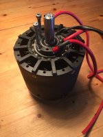
It could've been a hallelujah moment tonight.
image.jpeg
But the phase wires still doesn't fit as there's a flange on the bearing seat for the big bearing that is wider than the bearing.

I'll have to open it again, mill down the flange on the cover and space out the bearing. I could've still managed if i'd squashed the phases flat and put the coil wires on the sides of the 8awg when soldering the first time but that would still be tight.

I am considering to go back to 10awg and redo phase soldering, it really doesn't make a big difference for the total performance.
 
those high flex silicon wires are quite large in diameter.
when i was upgrading the wires on a hub motor i was using PTFE insulated wires for highest possible cross section (most hub motors are already equipped wich such).

now i'm really excited about the new motor data and how it performs :) good job!
 
@madin :It's a combination of too much added copper and too little space :D

I removed the large bearing and found it was crunching quite a lot. It's a quality NSK bearing but it's only sealed ZZ (metal plates) so i guess the chain has put gravel and salt into it last winter.

I ordered a new bearing from vxb bearing: 61810-2rz
It's 5mm thinner and only 65 OD. I'll make a shim ring for it that is 65/72mm and 7mm thick.
It has two low friction rubber seals. An SKF bearing of this type adds only 5W drag at 3000 rpm, very low!

I'll check the space for those of you that won't change bearing type. I think it's possible even without the milling of the bearing seat..

It won't be possible to squeeze the end turns to get more space, only by squashing the phase leads better. We'll see.
 
Should have left the windings long, so you could just bring them all the way out of the motor with a simple layer or two of shrink wrap for extra protection. With your flat winding wire you could have gained all the clearance you need. When it's your own motor for a custom install there's no need for flexible wire until after the motor. Since motor wire is already insulated, you can combine all 3 phases for getting phase leads out of a motor for maximum copper using minimum space instead of wasting it on bulky insulation and/or fine copper wire.
 
Back
Top