Cycle Analyst V3 preview and first beta release

Tek, Justin, et al.

Since doing "Windows desktop support" is near the top of everybody's list of 'most fun' things to do, here's an opportunity. I yesterday downloaded the latest CA setup utility from the Grin page (per Tek's post above) and installed it per usual methods. After installation -- which went fine -- the program reported being version 1.43, and defaulted to the b20 hex firmware file. I currently have four CAv3 units in play for various projects, so I was going to update all of them from their current b15 firmware versions.

I first installed 1.43 on a Win7Pro box (OS is 32 bit, but Dell Optiplex 780 is 64 bit hardware). I accepted the default b20 setup file, changed several values, and 'saved as' a new custom file. When I got down to the PASD section, made some changes, and did a Save (via Ctl-S on keyboard), and the program crashed (popup window, "CASetupUtility.exe has stopped working". I can provide additional details about crash details, but it pointed to a problem with "ntdll.dll". The edited values actually got saved, including the last change prior to the crash. I could restart the program, reload my edited file, and continue ... unitl the next Save, which led to another crash. Not the most useful way to proceed.

I downloaded the same 1.43 to an old Toshiba laptop running WinXPPro, which is my main machine for programming the CA's, and got exactly the same behavior as above, including the crash details pointing to the ntdll file. Actually, the crashed happened sooner, so I know the failure isn't specific to the PASD section data changes.

I tried running the program both as the user who installed the program as well as in 'administrator' mode, so I don't think it's a "permissions" thing -- especially since all changes were duly saved to the new files on the disk.

All previous versions of the setup utility have worked just fine for me, including the last previous version before this new 1.4* series. I did not install the 1.41, or the 1.42 if there was one. On the old laptop I had to tweak the communication parameters on the programming link to accommodate for a slower CPU, but all has been fine since.

I can try to install the Linux 1.43 version, but I'd prefer to get it running on my old laptop, which already has a place in my ebike toolbox. I can also install on a Win10Pro laptop to see what happens, if you want me to.

Thanks!
 
hey rb-
Thanks for the heads-up on this. I will cut a ticket for the problem to get this in the pipe for repair.

I confess to still being on 1.41 on my development machine (WinPro7 32bit, Dell Latitude D630) which seems to generally be behaving itself -- I guess procrastination has helped me dodge a bullet on this later version.

teklektik said:
The next 3.1 release will be 3.1b21 which definitely has a new EEPROM map and will require a fresh setup. Since there's no functional difference between the previous 3.1b16 and the new 3.1b20, there's no compelling feature or performance reason to update between these versions in advance of b21.
  • I expect release of 3.1b21 shortly. We've been struggling with a nasty bug that really upset the schedule, but it looks squashed as of yesterday so hopefully we just need to tidy up details, package, and alpha test.
I mention this so that folks considering a change to b20 may better wait a short bit to avoid another round of parameter entry. Regardless of these newly reported 'settings configuration' issues, a 1.4x installation will still flash the new b21 firmware.
 
mrbill said:
Yes, I use the same potentiometer model, purchased at the same time, on the bike that is not experiencing problems. Also the same controller (ASI BAC2000), motor (Edge 1500 w/Statoraid and Hubsinks), and CA3 (at firmware revision b16 (now x16 on the problem bike)) are on both bikes, connected in the same way. There could be unit to unit variability somewhere that accounts for the abnormal display behavior. But my two bikes are configured as closely as possible as this makes it easier for me to keep the settings and firmware (both controller and CA3) up-to-date.

I need to post a correction. What I said above isn't quite true.

The CA3 on the bike on which I have observed the unbidden AuxA pot display problem was modified by me (per Justin's approval in this posting: https://endless-sphere.com/forums/viewtopic.php?f=4&t=37964&start=3525#p1263928) to enable the red backlight LEDs by placing a solder bridge across the recommended pads on the CA3 board. In so doing I also left the white LEDs in-circuit.

Can this modification introduce noise sufficient to cause an unbidden AuxA pot adjust screen to appear?
 
mrbill said:
The CA3 on the bike on which I have observed the unbidden AuxA pot display problem was modified ... to enable the red backlight LEDs by placing a solder bridge across the recommended pads on the CA3 board. In so doing I also left the white LEDs in-circuit.

Can this modification introduce noise sufficient to cause an unbidden AuxA pot adjust screen to appear?
Nope. That's just a bit of steady DC load with no switching, etc to create noise. In your case, I suspect the long CA-DP run is picking up some controller or phase wire noise along the way, or the controller itself may be injecting it directly onto the CA-DP lines. In any case it's extremely unlikely that the origin of the noise is the CA or its accessories.
 
This may not be the right thread to post this under, and if so, I'll learn how to move it to a new/different thread. What I have is the following question:

Is it possible with the current CAv3 firmware/hardware to have a TORQUE ONLY sensor input setup? (i.e., no PAS info at all).

1. The ebike in question is a "Rowbike" (rowbike.com) prototype. Given it's architecture, it has no pedals (and no bottom bracket) used for propulsion. It uses a 'power lever' which has a cadence of sorts, but I don't want to monitor that, at least not yet.

2. The torque signal comes from four strain gauges I have mounted in a Wheatstone bridge configuration on the steel handlebars, which are pulled by the rider to create propulsion. The strain gauges are supplied by Justin, as he uses these in the same type of torque reading setup on his electric longboard (discussed on another thread here on ES). This part is working extremely well, thanks to wonderful support from Grin.

3. The electric assist is provided by a Crystalyte HT3525 rear hub motor radially laced in a 20" wheel. Power comes from a 48V (13S) eZee 10.5AHr Li battery pack, and is controlled a Grin Phaserunner (had been a Lyen). With Schwalbe Big Apple Plus tires, this setup is powerful enough to tow a car, so clearly my design suffers from overkill thinking.

4. The strain gauge low level signals are amplified/conditioned in either of the following methods while developing this prototype:
a) A "Grin Strain4" dual op-amp board designed and created by Justin for use in the StokeMonkey conversion kit, and used in other very interesting prototype projects he's doing; and,
b) a instrument amplifier based (INA122) board I and a colleague developed, which is a simpler amp than Justin's board because it ignores all of the PAS (RPM, Dir) parameters and voltage regulation. It also uses a dual op-amp to help get the output voltages into the analog throttle range needed.

Ideally, I would like to simply go into the CAv3's PASD (PAS Device) section, select a "Custom" device which would do the current voltage to Nm conversion just as it does now, and have the CAv3 send a standard throttle signal to the Phaserunner. I'd like for all of this to happen without any reference to PAS parameters. To get the 'human watts' values, I suppose I would take the Nm torque value, which represents how hard the rider is pulling on the handlebars/power lever, and combine it with the time over which the force is applied. This metric isn't critical to the project (yet).

When I take the output of the strain gauges and run it through our amplifier, I can tweak the amplifier's gain and voltage reference offsets to mimic a typical throttle range of about 0.85-4.00 volts, and use this setup as a somewhat standard throttle. However, I want to be able to continue using an actual separate dedicated throttle, and have my torque signal go into the TRQ (green) wire on the CA's PAS connector, and have the usual benefits of the CA's management abilities.

I'm hoping that I'm missing something obvious here, and don't really need to 'fake' a PAS cadence/pulse input to get a proportional assist based solely on the torque signal from my strain gauges. I'm pretty sure Grin has a way of accomplishing this, because I think that even as I type this (Jun 10), Justin is up in Vancouver at a "Main St" event, demo-ing a new version of his electric longboard which uses technology which I've been copying/mimicking/stealing all along, and I don't *think* he bothers with PAS data on the longboard... :)
 
hey rb-
First, you must realize that we can cook up custom firmware for any of the projects, so it's not useful to try to draw conclusions about what the CA3 can do compared to other products/projects (e.g. the skateboard or power unicycle).

Anyhow, the CA3 is specifically designed to demand pedaling for assist power to be applied - which is a design criterion that is exactly the opposite of what you want. So on the face of it, what you propose will not work. That said, it would be trivial to synthesize the requisite signal and gate it on/off based on the torque input- likely just a single chip. Faking 'no pedaling' is not strictly required, but this more abruptly terminates power where the power PID controller might otherwise require some time for power to wind down by just removing the torque input (i.e. assist lingers if you suddenly faux-pedal but stops quick-like if you stop pedaling). Here you can see how the logic is designed around a more holistic view of pedaling activity, not just detection of a single aspect.

From your moniker I have to wonder if you are affiliated with rowbike.com. Since you've already been in contact with Justin for hardware bits and pieces, if you have a business enterprise in mind, you might discuss with him a custom OEM CA3 to address your specific needs. We can do derived special OEM versions - and in this case it's much easier to develop a custom version by deleting code... :)
 
rowbiker said:
This may not be the right thread to post this under, and if so, I'll learn how to move it to a new/different thread. What I have is the following question:

Is it possible with the current CAv3 firmware/hardware to have a TORQUE ONLY sensor input setup? (i.e., no PAS info at all).

As Tek said the short answer is no, but the rationale wasn't fully explained. There are two main reasons why the current firmware has a requirement of both torque AND pas/cadence signals to operate:

#1) The torque PAS modes are operating in a power multiplication circuit, so the CA3 regulates things so that the electrical power going to the hub motor is in direct proportion to the human power going into the pedals. In order to do this calculation we need to know the human watts, and knowing the human watts requires the CA have both the torque and the RPM of the cranks. With a torque signal alone, you could just stand on the cranks without turning them and get full power
#2) As a safety features, the offset or zero point torque of many torque transducers can drift around quite a lot and are not especially stable. So if you turn on an ebike and the torque sensor is say 2.58V instead of the 2.50V it was when the offset was calibrated, then that could be enough of a torque signal to cause the bike to take off on it's own if it was purely torque sensing. Much worse is if you get water ingress, a cable disconnect or severed wire or anything else that can cause the torque signal to go way up to like 4-5V. By requiring that the pedals are also turned, then even even if the torque signal goes wonkers or just drifts above the zero point the power will always stop once you stop turning the cranks. It's a really good safety cutout for sensors that are not exactly the most reliable.

That said, there are some ebike torque sensors on the market, like the TMM4 dropout sensor or the stock BeamTS chain tension sensor which don't intrinsically have any PAS component to them, and I'd like to make the CA3 generally compatible with these too without the inconvenience of also needing to wire up a separate PAS disk on the cranks. So when that happens, you'll have you dream with the stock 3.1X firmware build.

In the meantime though, there are a couple fairly easy things you can do with various levels of hackiness but that could let you move forwards with the design experimentation:

a) Hook up a simple PAS sensor disk and pickup to any pivoting component of the rowbike and use the regular PAS plug of the CA3 for both your strain gauge and the row sensing. This has the great safety advantage of #2 and could allow for reasonably accurate human watts info too if done correctly.

b) Connect a simple peak detector circuit (super trivial diode + capacitor) on the output of your strain amplifier circuit so that it has an output voltage which more or less keeps track of the peak rowing force. Then use this as the throttle input signal for the CA3, and also connect it to your ebrake so that the signal immediately goes to ground when you brake. You can hook up a normal throttle in parallel with it no problem, and then the higher of the two signals (throttle vs peak detector) will be the one that dominates and makes it to the controller.

c) Similar to a), but instead of hooking up a PAS sensor and magnet ring, you could instead just short together the speedo input of the CA to the RPM pad of the PAS plug, and that kindof simulates a pas cadence signal without any new sensors on the bike. It does have the safety of preventing the bike from taking off when it is just powered on and there is a high torque signal reading, but once the bike is moving in this situation then you'd have the runaway rowbike.

d) you _could_ also just go ahead an use the electric skateboard CA3 code. I'm about to start a new thread on that and will post the .hex file for anyone to play with. It re-purposes the Aux and Trq lines to be front and rear weight signals, and then outputs a voltage based on the difference between these two values and a scaling factor (in mV/lb). The downside is that it is quite responsive so you'll have pulses of power while you are on the pull stroke, and then no power during the recovery phase, unless you set up the CA3's output to have a really slow throttle down ramp rate. It would definitely want the use of a torque based motor controller (like a Phaserunner or adaptto etc).
 
Wow!! Even though I've developed unreasonably high expectations over the past several years from both Grin and ES (Tek! et al.), I'm constantly blown away by the size of your souls and intellects. It's hard for me to express how empowered I feel with the work I'm doing, benefitting from such resources...

There is so much information in the above two posts that it will take me several days to aborb it all, but my initial take is that the 'skateboard solution' is what I'm after. I've followed Justin's longboard project as closely as I could since 2014, and it's always struck me as so simple and elegant that it must just be magic. I (of course) quickly realized that it just *looked* simple, with lots of devils in plenty of details. The safety concerns never quite made it to my to-do list (just like documenation for new software programs) -- something to be looked at after the prototype was done. Justin's approach of incorporating safety into all design phases is of course the only sane way to do this.

After Tek's post, I'd been leaning towards 'faking' the PAS signal with some kind of voltage controlled oscillator, much like the circuit Tek uses in his ebike/CA input simulator. This may still figure into the final solution, especially when we get to the human watts calculation, which would be nice to have, but not immediately necessary. However, a 'pure' torque solution, based entirely on the pounds of pull the rider exerts on the power lever, is really the initial target.

I'm also working on a parallel prototype project which involves an airborne recumbent ebike (see skyridetechnology.com). It is relatively simple in that it uses 'traditional' pedals, so I used an off-the-shelf TDCM bottom bracket, fed into a stock CAv3, hooked to a Grinfineon controller, which drives an Israeli RV-120 motor inside an overhead track. This is a fly-by-wire system, so the pedals are hooked up to a simple resistance unit (specially wound automotive alternator) which at this point simply dumps the rider's energy into several incandescent light bulbs. It will do regen when I get around to it. The TDCM supplies both torque and PAS signals, and Grin/Tek have thoroughly documented how to program this setup with the CAv3 -- which works very well, thank you.

The rowbike doesn't have pedals of any kind, and therein lies the rub. The powerlever cadence is really too low to be useful as far as I can see, except -- as Justin suggests -- that it can confirm that there actually is a rider on the bike, and it's alive. Not to be trivialized! :)

The pure torque solution of the skateboard, with the rider shifting its weight, has always struck me as the one that give the rowbiker the best experience, since there's nothing to 'learn'. The machine responds to the rider's natural movements, simply making the rider feel more powerful. Justin elegantly explains this idea somewhere in an ES thread.

I'll look forward to Justin's thread on the 'Skateboard CA" code, and will try that. I find the "hackiness" of all this positively thrilling! I think "responsiveness" to the powerlever pull is a great thing, and no assist during the recovery phase of the lever is totally acceptable.

P.S. Justin -- I was totally and pleasantly surprised on my most recent birthday (of which I've had quite a few) by a maroon garment, made of an exquisitely knit cotton, with luminescent lettering describing my favorite kind of 'thinking'. Given to me by wife of 40 years (Debora Slee), it was made possible by Justin having mercy on her and making it possible for her to surprise me with it. Again, more bounty than I deserve, but I *am* grateful for it all.
 
rowbiker said:
The rowbike doesn't have pedals of any kind, and therein lies the rub. The powerlever cadence is really too low to be useful as far as I can see, except -- as Justin suggests -- that it can confirm that there actually is a rider on the bike, and it's alive.
You can use a "linear" "cadence" sensor, with a strip of magnetic poles on some fixed point on the frame that the "oar handles" ;) pass on each stroke.

If the stroke speed is not linear in nature, then to get a linear output, simply space the magnets appropriately--closer together where the stroke is faster, farther apart where it is slower, so that the pulses from it occur at the same intervals.

The more magnets, the more "poles" of the signal.
 
That's a great idea, amberwolf, especially for a new design we're working on which has the power stroke being more linear than it is now. The power lever ("oars") now pivot on a single shaft/bolt, so the handlebars travel in an arc. We're aiming for a more linear pull from front to back, and critically placed magnets on the frame, with a Hall sensor on the moving power lever, would be capable of providing very useful PAS data.
 
My second position Pot adjust appears all the time while the switch is in that position. Nothing is actually changing to affect my ride but I can’t see any other info which is quite annoying.
Why is this happening is there a way to fix it or as a last resort a way to fully disable that screen form ever appearing?
Thanks!
 
Unfortunately there's presently no means to deactivate that pop-up or make it less sensitive.

A couple of users have had this problem - it traces down to electrical noise that tricks the CA into thinking the AUX POT signal is changing. Putting a 0.01uf cap across the AUX POT input and GND pad on the PCB should bypass the noise and get rid of the spurious pop-ups.

We've discussed some Setup control for this in the past but it wasn't too pressing - maybe the matter needs to be revisited...
 
teklektik said:
Unfortunately there's presently no means to deactivate that pop-up or make it less sensitive.

A couple of users have had this problem - it traces down to electrical noise that tricks the CA into thinking the AUX POT signal is changing. Putting a 0.01uf cap across the AUX POT input and GND pad on the PCB should bypass the noise and get rid of the spurious pop-ups.

We've discussed some Setup control for this in the past but it wasn't too pressing - maybe the matter needs to be revisited...
Thanks for the quick reply! That sounds easy enough to try out. Perhaps this happens on higher voltage setups? Seems to be more noisy when my batt is fully charged to 84V.
EDIT: I have added the CAP and it works perfectly no more nagging, Thank you again!!!. Another reason I may have noise is that my throttle and POT use the same ground pin, perhaps that adds noise.
 
Hi. I think my Cycle analyst was shorted by piece of solder what i found in factory sealed case. So polarity protection D3 is burned, Q1 fet have little dot on front of case and mabe Z1 zener(F4 type smd). Hope isnt burned anything else... Ive used new analyst only in dry conditions, for 3-4 months, without any modifications, with only one connection to original CA shunt as measuring device. :cry:

I think D3 can be any standard diode in 100+V, but i cant find where to buy right type of Q1 in europe(czech republic) with reasonable postage fees. ( i can hardly read on case SI DN2450 161768W ) Do you have some spare parts? If is in this thread grin tech support, I wrote you an email.

Thank you very much!
EDIT: add picture and part names correction
1o0iag.jpg
 
Cycle Analyst 2.4 HELP!

I'm trying to assist a friend an have only CA3 displays for experience.

It appears the CA 2.3 2.4 has no PAS sensor option? Am I correct?

Thanks!
 
The manual states that you shouldn't change to high range mode after you've made other settings. This seems like good advice because I got weird behavior after doing so. I found out about the mode after I've done the configuration and after changing to high range, the bike has very little power. It's super weak.

I'm going to do a total reset and configure the high range setting first thing, but I'm curious to know what causes the strange behavior if anyone has more info.
 
tomjasz said:
It appears the CA 2.3 2.4 has no PAS sensor option? Am I correct?
The image below shows the CA 2.3+ PCBs compared to the CA3 - essentially stripped down versions.
Thermistor, Throttle, and PAS inputs are absent.
No PAS settings in the CA2.4 manual either... :)

CA3vsCA2pcbs.png
amberwolf said:
Yeah, all the control options (vs just monitoring) came with v3.
Not really - that statement is perhaps misleading in its generality...

The CA2 operates by 'limiting' the rider throttle and by that means provides LVC, speed, and max current control - definitely 'controlling' the controller. If the out-of-box connections are changed slightly as described in the manual, it can provide Current Throttle to the controller similar to the CA3. While it's true that many folks post here as if the CA2 is just a 'monitor only' expensive voltmeter, its important features work by controlling the controller.

The CA3 directly provides the controller throttle (instead of just limiting the operator throttle) making the handlebar throttle essentially fly-by-wire while also allowing integration of PAS, ebrakes, etc. So, more and better control than a CA2...

  • EDIT: Perhaps more succinctly and what you were getting at: out-of-box the CA2 asserts control (suppresses user throttle) when monitoring indicates something has gone out of bounds while the CA3 has direct and exclusive throttle control at all times as determined by monitoring and the extra inputs (user throttle, ebrakes, Aux switches, PAS, temp sensor).
 
I have a Phase Runner paired with a CA3. But the two seem to slightly disagree on Wattage being used. Controller says I am at 3000W but CA3 says it is around 2750W. It seems to be a difference in Amperage measured. Which one do I trust more? I am assuming I need to Calibrate the CA3.
 
brickwall said:
The manual states that you shouldn't change to high range mode after you've made other settings. This seems like good advice because I got weird behavior after doing so. I found out about the mode after I've done the configuration and after changing to high range, the bike has very little power. It's super weak.

I'm going to do a total reset and configure the high range setting first thing, but I'm curious to know what causes the strange behavior if anyone has more info.

So I did a complete reset and redid the setup process. Same issues.

Specifically, the bike performs like it's highly limited even though the imposed limits are well above what the bike can do. Setting a 15 kW power limit makes for a smooth and pretty relaxing ride, as does limiting the amps to 160. That shouldn't be the case with a bike that instantly wheelies from standstill when unlimited. Maybe I'm missing something, or there's a bug in there somewhere.
 
Not really sure where you are going with that post...

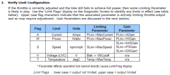
I can only say that if you carefully follow the installation instructions in the Guide, then you will come to the section about checking for full power and examining the Limit Flags to identify what might be causing limiting. This section is there to address your issue specifically.

LoPowerHelp.png
Additionally, if your bike achieves full power - but (too) slowly/smoothly - then you may have a throttle ramping issue. Ramping adjustments are discussed in the installation section immediately following the section on checking Limit Flags.

If you didn't do the step by step installation, then you need to reset to defaults and start again. If you did all the steps *exactly* AND if you have no Limit Flags set but the bike performs smoothly and does not cutout (DSGain speed limiting) AND if setting the UpRate to the highest speed does not help, then you need to contact Grin since the speed limit would not appear to be caused by firmware.
 
teklektik said:
Not really sure where you are going with that post...

I can only say that if you carefully follow the installation instructions in the Guide, then you will come to the section about checking for full power and examining the Limit Flags to identify what might be causing limiting. This section is there to address your issue specifically.

Additionally, if your bike achieves full power - but (too) slowly/smoothly - then you may have a throttle ramping issue. Ramping adjustments are discussed in the installation section immediately following the section on checking Limit Flags.

If you didn't do the step by step installation, then you need to reset to defaults and start again. If you did all the steps *exactly* AND if you have no Limit Flags set but the bike performs smoothly and does not cutout (DSGain speed limiting) AND if setting the UpRate to the highest speed does not help, then you need to contact Grin since the speed limit would not appear to be caused by firmware.

My point is the limits in high range mode make no sense to me. 15 kw should be well above what the bike can perform, yet limits performance similarly to what i get with 5000w in low range mode.

In other words, setting the exact same limits in the different range modes yields different results (e.g 9000W in low or 9kW in high). I am clueless.

EDIT: Maybe this is it!
Scale up the default values of PLim->AGain and PLim->WGain by 10x or set to 999 if the scaled value is 1000 or greater and cannot be entered into the Setup screen
I might have missed this during the setup and left them on the defaults. I'm not able to check now, but scaling them to 10x might solve my issue.
 
After adding a Cycle Analyst V3 to my ebike and setting it up per the manual it has an odd behavior. If I slow, which engages the ebrake, then apply the throttle it will intermittently not respond. Appling the ebrake momentarily again seems to reset the system and I can apply the throttle normally. I have watched the status screen when this happens and no limiting flag seems to be activated. Any ideas as to what I can do to troubleshoot?
 
Hey S-
Okay - sounds like you went through the installation ritual - good... :)
Here's some stuff that may help fill in the blanks about what's going on:

Some questions to help clarify things:
  • What version of firmware are you running (see splashscreen)?
  • What Throttle Mode are you using (PassThru, Current, Power)?
  • Where are your ebrakes connected (controller, CA, or controller + CA)?
  • If they're attached to the CA, (just to check the obvious) does the Main Screen ebrake Glyph always appear/disappear exactly when you apply/release the ebrakes?
  • Take a look at the Diagnostic Screen when your throttle fails to respond.
    1. Does the Throttle IN field vary as you turn the (non-functioning) throttle?
      If so, the throttle signal is getting to the CA okay.
      If not, the throttle signal is somehow being compromised before the CA (this seems unlikely, but let's check the IN field just to be thorough...)

    2. Does the Throttle OUT field vary as you turn the (non-functioning) throttle?
      If so, the CA is sending a throttle signal to the controller but the controller is ignoring it.
      If not, the CA somehow probably thinks the ebrakes are still applied and is suppressing the throttle.
 
Back
Top