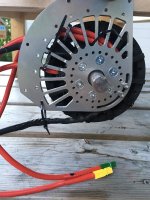
Idiots guide to rewinding Revolt 120 pro

I found info that a switch from star to delta connection for a motor gives a phase delay of 30 electrical degrees. I think it is explained by a different coils induction from the three coils connections in delta as compared to two coils connections in star.

If there's a good reference to this with explanation then please link it!

:?: could this explain why original hall sensors are off for the Revolt RV120?

My thinking is:
Tuned setting for phase shift when optimized with an adaptto controller was 24 degrees, error margin to 30 is 6 degrees and the sensors were offset by some millimeter in the slots which could cause these 6 degrees. It roughly fits..

My guess halls for the RV120 are set neutral (as they are placed 120 degrees apart in the middle of the slots - no physical shift) and should be shifted 30 electrical degrees. That would be a really basic error if this is the case.

I will try the outside halls with 30(electrical degrees)/7(pole pairs)=4.3 degrees mechanical delayed hall location.
 
I checked the web, could find a lot of discussions on the diff between delta and star for transformers but none that i easily understand.

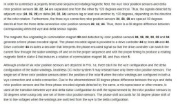
This patent (US6493924) shows the diff and the resulting 30 degree shift between wye and delta:
patUS6493924.JPG
I found that (as many times before) some quite well known names on ES ( LFP, methods + others) were ten years ahead of me discussing it in the hall sensors thread: https://endless-sphere.com/forums/viewtopic.php?f=30&t=9061 :wink:

The physical location of the halls in the Revolt RV120 motors are neutral - even if they would be placed well in the slots they are still shifted 30 degrees electrical from where they should be for optimal performance. It is quite a lot as one commutation step covers 60 degrees until next step.
 
Vxb sent me the wrong bearing... I couldn't wait for a new one from them so i bought an SKF one. It'll be better quality anyway, so i guess it's worth it.

Milled cover bearing seat:
image.jpeg
I glued shim ring stock to a wood sheet to keep the finished ring from flying off at the last cut. Worked well! I dissolved glue with acetone after the milling was done, could pop it loose after some minutes.
View attachment 1
I got a good press fit between bearing and ring:


Soon assembly time again :D
 
I tried to shift the RLS encoder i use on my bike 30 degrees as i thought my bike might also be affected by the y-->delta shift. It did not work.

I thought about it and it's clear why: even though magnetic field in delta connection differs from wye in 30 degrees electrical it does not matter for the encoder. This is beacuse in order to set the zero position of the encoder you energize phase 2(as +) & 3(as -) to get the rotor to move in the correct position, then zero it by shorting two pads on the encoder. See commutation table:


This zero position of the encoder is correct in relation to the magnetic field as it's the magnetic field that determines where the rotor is. Easy (and i guess trivial for some of you..)

This also means that in order to set the external halls position of the new motor i can just energise phase2&# in the same way and shift the hall slider until it switches to show 1-0-1 for the hall signals.

If the external sensors don't perform i'll just buy another RMC22 encoder as it works really well!
 
Assembled! Had to put the bearing in the freezer and the end cover in the oven to get the cover on and bearing pressed in. 80 degrees temp delta makes it a lot easier! :D

Now the hall connections and phase connectors are next.
 

Attachments

  • image.jpeg
    image.jpeg
    81.9 KB · Views: 3,161
I watched user nextEV:s videos on youtube. It seems more people are running into problems with Revolt motors:
https://youtu.be/wRI_5cF3nUY

The testing shows high noload currents and heating issues with RV160 motor and in the comments you can read about bad hall interference.. Sounds familiar.

One thing that is really bad for my rewind result is that the rotor temp in their testing gets higher than the stator due to eddy current losses. I've noticed the same but did not think too much about it.. But it means that even if i lower losses in stator i still will keep the losses in rotor and they will be the majority. Damn!
 
What's your rewind going to do to KV?

If your torque/amp has gone up substantially and your KV has dropped, you may have both decreased your iron losses and reduced your copper losses substantially.

Given your increase in fill factor, you may also be able to gear taller, reducing your average RPM while still having more than adequate wheel torque (and giving yourself a wider speed range for top speed runs)
 
Rewind should not change kV. It's true i could change the gearing to use the motor at lower RPM with more current, normally that would not be the best..

Magnets could be segmented to lower the eddy currents, but that's a big and expensive update needed together with a rewind.

Let's see how bad it really is..expectations on result from rewind are lower now.
 
It's not really (just) eddy currents in the stator in the case for revolt motor. RV 160 has 0,35mm laminations which should be OK from what i've read.

Since rotor gets hotter than stator it's rotor eddy currents that are the cause. I think mainly eddy currents formed in the magnets since they are closest to the coils. Large magnets allow large eddy currents and could be avoided by segmenting magnets - the papers i've read show that by dividing magnets it's possible to lower eddy losses in rotor to 50%, even 25%

It's affected by the harmonics in the motor from slot/pole combinations and slot opening design etc etc..too complicated to improve, design needs to be optimized at manufacturer.
 
Larsb, did you notice when motor is taken apart, no metal sticks to rotor. No magnetic leakage.
As soon as you assemble the motor the rotor picks up everything as hell. You can even lift the hole motor weight by just magnetic leakage of rotor with some metal put near rotor. Something here is definitely not right when that stator meets the rotor.
Also in my previous posts I did mention this and also bigger temperature at rotor even at free spin after less then one minute.
 
If i get too much free time during the summer vacation i'll try a flux jacket on the motor to see the effect on kV :D
..it won't help with the heating of the stator though..

I think revolt should have spaced the magnets a bit, they are right against each other causing stray flux.
 
larsb said:
If i get too much free time during the summer vacation i'll try a flux jacket on the motor to see the effect on kV :D

good idea
as for the magnets if understand right: there might be a chance to find a size that fits, because if you split them in segmetns (3 or 4?), a bended shape wouldn't be absolutely necessary anymore (i think of joby motors which have two rectangular magnets side by side).
 
image.jpeg
I got the motor running tonight!! :D :D :D :D :D
https://youtu.be/tAtl2nrKlKA

KV is 41.5 now vs 45 before so i might have gotten an extra turn on.
Noload current 7.2A@71V (is the best i've gotten)

Even though i moved the halls around quite a bit there was not a big difference in current. I prepared the halls with pigtails to do a scope readout later to get optimal location.
It's still a bit over 500w losses at no load!

After a short run it shows why. Rotor is warm to the touch and coils are cold like the outside evening. Coils can take 200 degrees and magnets 80-120 so it's really bad news

If i could get a new rotor shell then i might try to glue some magnets but isn't that too much like turd polishing!?
Magnets 50x5x3 mm would fit well and it would be like splitting the existing ones in 5.
 
I think you have already passed the point of no return regarding the manhours you put into this motor. If new magnets and jackets is what it takes to make it works I say go for it, at least that way you get the satisfaction of getting a lightweight and powerful motor as intended when you first placed your order.

I do hope Revolt is keeping an eye out on this thread, maybe they will consider doing a run of more e-bike specific motors as the revolts of today seems to work better for RC air crafts then e-bikes.
 
What a shame that the rotor gives such high losses. But surely explains the high loses at no load.
I think the magnets + jacket is a small job compared to what you already have done.
As usual there is more to it than first expected, I recognize this from many projects...

Anyhow it has been a pleasure to follow the progress so far, and I hope you can find time to correct the last bit!
 
larsb said:
If i could get a new rotor shell then i might try to glue some magnets but isn't that too much like turd polishing!?
Magnets 50x5x3 mm would fit well and it would be like splitting the existing ones in 5.

I would ask revolt for the grade of the magnets first, and than look if there are segmented types available.
Keep in mind that you can leave a gap between the north and south groups, because the fields are just cancelling out there and it would be useless to place them side by side (FWIK thats done for cheap and simple assembling process).
Higher temperature rating would definitely make sense, and probabaly also a lower strength to reduce the eddy losses. You anyway have improved torque losses so much so you could put up with a little lower kT for gaining RPM
 
I've been reading up on rotor material and it seems like rotor backiron material also does matter for the losses. From the research papers i've come across it's clear that the losses can be large in rotor backiron but how extreme or representative their researched motor types are i can't judge. Some stainless steels have large hysteresis losses and what Revolt used is not known..That makes the effort to change magnets in existing rotor shell doubtful.

My preferrred route then would be halbach array ironless rotor if i did it. But that would be a gamble - as would the other option to change just the magnets.
Where would one find a suitable material like glassfibre reinforced high temp epoxy tubing.. It's got the true "unobtanium" shimmer to it :D

It's got to be taken to the realistic level, suggestions are welcome :D
 
larsb said:
I've been reading up on rotor material and it seems like rotor backiron material also does matter for the losses. From the research papers i've come across it's clear that the losses can be large in rotor backiron but how extreme or representative their researched motor types are i can't judge. Some stainless steels have large hysteresis losses and what Revolt used is not known..That makes the effort to change magnets in existing rotor shell doubtful.

My preferrred route then would be halbach array ironless rotor if i did it. But that would be a gamble - as would the other option to change just the magnets.
Where would one find a suitable material like glassfibre reinforced high temp epoxy tubing.. It's got the true "unobtanium" shimmer to it :D

It's got to be taken to the realistic level, suggestions are welcome :D

As long as the rotor back iron is electrically isolated from the magnets, the greater proportion of the losses are likely to be within the magnets.

Laminating the back iron can reduce losses in some cases but I don't think that's worth pursuing.....

Forget the Halbach Array :wink:

Segmenting the magnets, axially or circumferentially is certainly worth doing. The greatest gain is to be had by segmenting the side of shortest dimension. The magnets need to be electrically isolated from each other, as well as from the back iron.

Measure the strength of the magnets if you want to replace them.

If you need a new can, you can just use mild steel tube.
 
Hallback array would steer magnetic forces towards the copper and not so much towards the back iron, right?
So assuming the material and or the thickness of the motors can is causing problems hallback array should rectify that? Or does hallback array bring new problems into account, problems that would be greater then the benefits?
 
Miles said:
Forget the Halbach Array :wink:
exactly! halbach motors usually have a high peak ETA and can do high RPM, but the torque is quite low (there is no stator iron)..
The magnets need to be electrically isolated from each other, as well as from the back iron.
makes sense. thanks for bring up that thing.
 
madin88 said:
exactly! halbach motors usually have a high peak ETA and can do high RPM, but the torque is quite low (there is no stator iron)..
You can design to achieve parity re. airgap flux density. It's more that the benefits, if any, wouldn't be worth the trouble, for a motor like this....
 
Back
Top