KT motor controllers -- Flexible OpenSource firmware for BMSBattery S/Kunteng KT motor controllers (0.25kW up to 5kW)

stancecoke said:
Are you still testing with the Cute 85? There are several reports, that this motor causes trouble at higher speeds even with the original firmware.
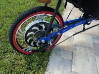
So, I found that Cute/Q85 don't have the hall sensors signals spaced at 60 degrees but I am handling it with success - don't known about original firmware.

I wounder if this motor have an higher eRPM and that means the hardware have low resolution for that, that get worst at higher speeds...

There is a reason why I am testing with this motor, because it is cheap, small and light. I would say most users go with such motor and so I would like to have firmware working well for it.

I know that I am not doing the PWM scheme as original firmware and I need to do that first. Unfortunately, my original controller with original firmware stopped working and I can't compare anymore. Need to buy another one but may take some time to get it.
 
stancecoke, for what I could understand from the german forum, you are now able to build and flash the firmware. What will be your next steps??

I want to make the firmware the drive well the Cute/Q85 and for that I will need to look at original controller and replicate it... I will be making some tests and I hope to learn more about the control for this motor.
 
casainho said:
stancecoke said:
Are you still testing with the Cute 85? There are several reports, that this motor causes trouble at higher speeds even with the original firmware.
I wounder if this motor have an higher eRPM and that means the hardware have low resolution for that, that get worst at higher speeds...

At very low speed:
41-9.png


At the max speed: 738 interpolation points / PWM cycles for each eRPM / 360 degrees --> 360 degrees / 738 ~= 0.5º for each interpolation point.

The PWM signals I recorded with Q85 at max speed - more pictures here: https://opensourceebikefirmware.bitbucket.io/Controllers--BMSBattery_S06x--S06S--PWM_signals--low_speed_up_to_max_speed_-_sineware.html
42-9.png


At the max speed: 28 interpolation points / PWM cycles for each eRPM / 360 degrees --> 360 degrees / 28 ~= 13º for each interpolation point.

There is no way to increase this resolution without increasing PWM frequency 16kHz (period is 64us). I don't know if hardware handles (I would say may handle up to 50us (20kHz) but I think the STM8 will not have enough processing to do the fast loop code at each PWM period. I heard that some expensive controllers do PWM frequency of 30kHz (period of 33us) -- still would be ~= 6.7º for each interpolation point.
 
casainho said:
What will be your next steps??

I'll try to add interrupt handlers for the PAS and the speed signals to derive the duty cycle value from wheels rpm, cranks rpm and crank torque (read in from throttle pin)
pmotor = f(phuman) = factor x torquehuman x rpm crank

There is already a set of S06S with a bottom bracket torque sensor at BMSBattery, but I want to be able define any characteristic between human power and motor power.
I already built a pre-controller (STM32 based) to manage this, but it's much smarter, if the original controller does this job :)

regards
stancecoke
.
 
casainho said:
At the max speed: 738 interpolation points / PWM cycles for each eRPM / 360 degrees --> 360 degrees / 738 ~= 0.5º for each interpolation point.

The PWM signals I recorded with Q85 at max speed - more pictures here: https://opensourceebikefirmware.bitbucket.io/Controllers--BMSBattery_S06x--S06S--PWM_signals--low_speed_up_to_max_speed_-_sineware.html
42-9.png


At the max speed: 28 interpolation points / PWM cycles for each eRPM / 360 degrees --> 360 degrees / 28 ~= 13º for each interpolation point.

There is no way to increase this resolution without increasing PWM frequency 16kHz (period is 64us). I don't know if hardware handles (I would say may handle up to 50us (20kHz) but I think the STM8 will not have enough processing to do the fast loop code at each PWM period. I heard that some expensive controllers do PWM frequency of 30kHz (period of 33us) -- still would be ~= 6.7º for each interpolation point.

As comparition, an Electric Unicycle Motor for which I developed FOC firmware, runs at 30km/h (14 inch wheel) but each eRPM takes 2.8ms (VERSUS the 1.8ms of Cute/Q85) -- it is 8º for each interpolation point VERSUS Cute/Q85 13º for each <-- that's not much difference...
 
stancecoke said:
casainho said:
What will be your next steps??
I'll try to add interrupt handlers for the PAS and the speed signals to derive the duty cycle value from wheels rpm, cranks rpm and crank torque (read in from throttle pin)
pmotor = f(phuman) = factor x torquehuman x rpm crank
I would avoid interrupts and why: I started to structure the code using different interrupts but I found they take to much time for the STM8 call and return them -- also I played with the priority of them but found that don't work as I expected -- the issue is that the fast loop motor control code needs to run at every 64us and any other interrupt seems to worst / delay the fast loop/PWM interrupt, which should be the top priority of the system.
What I am doing is using a timer on main loop and I will try call first in the loop the most priority code and counting the timer millis() -- I am doing this already to read the throttle value and do also the cruise control. This code do not interrupt the motor fast loop.
For code that needs to run each PWM cycle, I call it on the PWM interrupt or at multiple of the cycles.
For instance, I had interrupt for the pins of hall sensors signals and I removed the interrupt and I read instead the pin value at each PWM cycle. Anyway, later, when having motor code stable, we can measure all the times to understand all this things and see what is better.
But I think we should increase the PWM frequency if possible, to improve motor control for higher speed motors, and that means to optimize most as possible the PWM interrupt / motor fast loop.

For digital PAS signals, I would not use the interrupt of pins but the PWM / motor fast loop -- again, an pin interrupt would eat time of PWM / motor fast loop and probably be a source of instability on the motor control. If it is done on PWM cycle and with a known processing time, should be no issue. I would say: on PWM cycle looking for pin change value and flag / reset a timer variable; on main loop, look at the timer variable to find the PAS frequency and process it.

stancecoke said:
There is already a set of S06S with a bottom bracket torque sensor at BMSBattery, but I want to be able define any characteristic between human power and motor power.
I already built a pre-controller (STM32 based) to manage this, but it's much smarter, if the original controller does this job :)
GREAT!! Now I understand your motivation -- and I am tuned with you!! Making the firmware OpenSource as also documentation about the hardware, developers/hackers will be able to make new things!! -- and closed source firmware makes the systems very rigid and you need flexibility for your project / adding support to S06S/Kunteng KT controllers for the torque sensors.
 
stancecoke said:
I already built a pre-controller (STM32 based) to manage this, but it's much smarter, if the original controller does this job :)
Why do you prefer to write in german? Seems limiting to me, as simplified EN seems to be the Internet language -- for instance, the chinese like BMSBattery have their site in EN to reach all the world. I think your project, documented in EN, on Endless-sphere, would reach much more people. But I saw that you good many help on the german forum, that was amazing.
 
stancecoke said:
I already built a pre-controller (STM32 based) to manage this, but it's much smarter, if the original controller does this job :)

index.php


So I if the sensor measures bending and not torsion (I would guess the same principle as ultra cheap bathroom scales), I guess that wave form, the max value represents the time when the pedal is on lower side / near the ground.

I would read the ADC value (at each PWM cycle) and find the max of the signal as I once did to find the phase B current minimum value on the sinewave:

if (ui8_adc_current_phase_B_flag == 1)
{
// find the adc_current_phase_B minimum value
ui16_temp = ADC1_GetConversionValue ();
if (ui16_temp < ui16_adc_current_phase_B_temp)
{
ui16_adc_current_phase_B_temp = ui16_temp;
}
}

I would consider only the max value and so ignore the signal from the pedal that have the lowest max value.
 
casainho said:
I would read the ADC value (at each PWM cycle)

I read in a new torque value every rising edge of the PAS singal (32 pulses per crank revolution) an store it into an array. The duty cycle is derived from a mean value of the array. See my source code (simple text file).


casainho said:
For instance, I had interrupt for the pins of hall sensors signals and I removed the interrupt and I read instead the pin value at each PWM cycle

At your github repo there is the hall sensor handling still via interrupt?!

Code:
// HALL SENSORS signal
void EXTI_PORTE_IRQHandler(void) __interrupt(EXTI_PORTE_IRQHANDLER)
{
  hall_sensors_read_and_action ();
}

To improve time issues perhaps you shoud just set a flag in the interrupt routine and do the action in the main loop.

regards
stancecoke
 
stancecoke said:
casainho said:
For instance, I had interrupt for the pins of hall sensors signals and I removed the interrupt and I read instead the pin value at each PWM cycle

At your github repo there is the hall sensor handling still via interrupt?!

Code:
// HALL SENSORS signal
void EXTI_PORTE_IRQHandler(void) __interrupt(EXTI_PORTE_IRQHANDLER)
{
  hall_sensors_read_and_action ();
}
Seems you are still lookign at wrong git branch, probably at master. You need to look at SVM branch. Do you need help here?
 
stancecoke said:
casainho said:
I would read the ADC value (at each PWM cycle)

I read in a new torque value every rising edge of the PAS singal (32 pulses per crank revolution) an store it into an array. The duty cycle is derived from a mean value of the array. See my source code (simple text file).
Less useful to have comments in german :) -- but I think I got the general idea.
With your code with EN comments, in github, and with forum message / any documentation in EN, would be much better. What you did have great value!!! I didn't found yet anyone exploring and documenting this cheap/accessible torque sensors and make them working for general cheap EBike controllers.
What I mean as EN documentation, one of my big references: http://www.avdweb.nl/solar-bike/electronics/ku63-motor-controller.html

I understand that the PAS signal is there for compatibility and also to find the direction of pedaling.
The bending signal (https://en.wikipedia.org/wiki/Cadence_(cycling) ), should have no more than 120 rpm (0.5 rpsecond) = 500ms, 250ms each pulse. To avoid interrupts, I would read the ADC value every, say 25 times each pulse - this mean reading the ADC every 10ms and low pass filter with the mean value as you did mention. Good idea to low filter to get the DC value of the signal but still you don't get the max value, unless you multiply for some value... I still like the idea of reading directly the max value, as that is the max torque value. Low pass filter brings a delay... can you please tell me if your code works ok when the user hits for the first time the pedal when starting pedaling?? -- I wounder if this torque sensor is good for detecting the very first time when user presses the pedal.

stancecoke said:
To improve time issues perhaps you shoud just set a flag in the interrupt routine and do the action in the main loop.
For the motor control fast loop / PWM interrupt, I am calling the code on the interrupt -- it works ok and other firmwares like VESC and the Shane Colton firmware also does this way.
 
casainho said:
can you please tell me if your code works ok when the user hits for the first time the pedal when starting pedaling?? -- I wounder if this torque sensor is good for detecting the very first time when user presses the pedal.
In my code pmotor = f(phuman) and as phuman is zero as long as the cadence is zero, the motor assitance starts not with the first force on the pedal. But of course you can just take the torque signal to trigger the start of the motor.

casainho said:
Less useful to have comments in german
:D
If you are really interested, i can add english comments. But you can take a look at the code of the "Forumscontroller". Member @jenkie made his comments in english at github already :wink:

Regards
stancecoke
 
stancecoke said:
casainho said:
can you please tell me if your code works ok when the user hits for the first time the pedal when starting pedaling?? -- I wounder if this torque sensor is good for detecting the very first time when user presses the pedal.
In my code pmotor = f(phuman) and as phuman is zero as long as the cadence is zero, the motor assitance starts not with the first force on the pedal. But of course you can just take the torque signal to trigger the start of the motor.
Ok, good to know. I think in using torque sensor to help at the very beguin of pedaling.
Later, when having the controller working ok with PAS and throttle, I would like to have on my bicycles the torqie sensor -- I am very interested in having what you done :)

I really like to have documentation in EN about that torque sensor - is that ok if I copy-paste your forum messages to my note files and put on the HTML online?? Or do you prefer first to write it in EN?

casainho said:
Less useful to have comments in german
:D
If you are really interested, i can add english comments. But you can take a look at the code of the "Forumscontroller". Member @jenkie made his comments in english at github already :wink:
[/quote]
I am not interested for now because lack of time - I really hope you can develop for the S06S firmware and integrate on the firmware.
I would like to give you write access to the github project - can you send me your github user id?
 
casainho said:
I really like to have documentation in EN about that torque sensor - is that ok if I copy-paste your forum messages to my note files and put on the HTML online??

Of course it's OK to quote my documentation. But which torque-sensor do you think of? I've analysed several over the years :shock:

casainho said:
I would like to give you write access to the github project - can you send me your github user id?
I have no github user id yet. I even don't know how github works. I'm just downloading the source files an work with them offline...

I had a look at the SVM branch now, I have to say, that the master branch was much easier to understand :)
Why do you do the timing in that complicated way?! What does the cruise_control?.....

Why do you return a 8bit value from reading the throttle while the AD-Converter of the processor has 10 bit resolution?!

Code:
uint8_t adc_read_throttle (void)
{
  uint8_t ui8_temp;
...
  return ui8_temp;
}

regards
stancecoke
 
Which torque sensor are you using and why? Why did you make that project around that specific sensor??

Please create a github account. You can learn git as you are going. But for software and firmware projects, colaborative, is a must to use revision control as git.

What timmings do you refer?

Cruise control as on KU63: user keeps throttle constant for about 8 seconds and then it can release and throttle will keep that value until break or using throttle again. Very useful for develop as I only have 2 hands.

I try to have 8 bits to optimize the processing power sunce it is a 8 bits microcontroller. Also, removing the least significant bits is like a low pass filter.
 
I prefer the sempu sensor, I just buyed one from aliexpress (second generation). The principle of wireless signal transmission is the best i know and you have no mechanical parts that can lock due to corrosion/humidity.

If you just read in the Hibyte from ADC you have just 2bits resolution for the throttle value?!

regards
stancecoke
 
stancecoke said:
I prefer the sempu sensor, I just buyed one from aliexpress (second generation). The principle of wireless signal transmission is the best i know and you have no mechanical parts that can lock due to corrosion/humidity.
Wireless?? Hmmm, I need to read more about it!!!

stancecoke said:
If you just read in the Hibyte from ADC you have just 2bits resolution for the throttle value?!
It works because I need to play with left or right alignment on the ADC configuration!!
 
wireless i just the transmission from the rotating electronic placed on the crank axle to the static electronic of the sensor. The transmission from the sensor to the controller is by wire.

So you can configure ADC in that way, that the Hibyte contains bits 2-9 of the 10 bit word?

regards
stancecoke
 
stancecoke said:
wireless i just the transmission from the rotating electronic placed on the crank axle to the static electronic of the sensor. The transmission from the sensor to the controller is by wire.
I would like to choose a sensor the same way as the controller - the cheaper and easy to buy, like in one shop like BMSBattery. For instance, almost every online shop sell KT controller (S06S) and the LCD. I would like to choose the same sensor as the one that is in almost all shops -- can you tell me:
- which is the cheaper?
- which is the one that is most found on online shops?
- what about the one from BMSBattery? (They say it is needed a specific version of S06S that they aren't selling!!)

stancecoke said:
So you can configure ADC in that way, that the Hibyte contains bits 2-9 of the 10 bit word?
Yes.
 
casainho said:
- which is the cheaper?
- which is the one that is most found on online shops?
- what about the one from BMSBattery? (They say it is needed a specific version of S06S that they aren't selling!!)
You get several hits, if you search for "botton bracket torque sensor" at alibaba, but often, you have to order minimum 20 pieces or even more.
The one from BMSBattery is the cheapest andcomes in a set with a suitable controller (called "S06ST") and a LCD3 Display

In classical western "ebike-conversion-shops" these sensors are quite rare :-(. I know just one shop in germany.

regards
stancecoke
 
stancecoke said:
casainho said:
- which is the cheaper?
- which is the one that is most found on online shops?
- what about the one from BMSBattery? (They say it is needed a specific version of S06S that they aren't selling!!)
You get several hits, if you search for "botton bracket torque sensor" at alibaba, but often, you have to order minimum 20 pieces or even more.
The one from BMSBattery is the cheapest andcomes in a set with a suitable controller (called "S06ST") and a LCD3 Display
Ok, just understand that product includes the controller + LCD and the sensor.

I just contacted BMSBattery on the live chat and they told me they sell at unit the torque sensor for $50. Next time I just need to contact them again and they will sell to me. They say the connector/cable is different to the regular S06S and I will need to make the connector -- no issue for me and I will even document for other users.

Also I asked for the bluetooh module but they told me they don't have to sell at unit. Anyway, I am pretty sure we can make it DIY, just as you did using the step down voltage regulator + ardunio cheap UART bluetooth module.

Do you know of potential disadvantages of BMSBattery torque sensor?? -- because I think I will go with it because of lower price and availability from BMSBattery, at unit and that works with S06S controller.
 
Geege33708 said:
I wish I understood all this as I am not educated in this field. How can I learn?
Are you interested in some specific feature? Maybe you can gather information about it to help future development.
 
Ok here is the scenario- I have been an avid ebikekit.com fan for years, Jason Krafte and the tech guys are super. My problem has been that I am now on a tandem trike with my wife and it is just to much weight for the spoked wheels to handle. I decided to jump ship and go with GoldenMotors.ca I went with the cast aluminum motor/wheel combination and so far it has held up well. It took me awhile to figure out the spaghetti type controller and after taping all the wires up it looks good (homemade:) . The exposure to the elements has me concerned. The ebikekit controllers have always been packaged neat and away from the elements.
Does anyone know how I would hook up one of these controllers up to my Magic Pie 2. I have all the bells and whistles on the Golde Motor, but I don't need cruise control. The reverse is pretty cool though, I am looking for advice, Thanks, Geege
 

Attachments

  • sm1.jpg
    sm1.jpg
    57.7 KB · Views: 3,035
  • sm2.jpg
    sm2.jpg
    47.2 KB · Views: 3,035
Geege33708 said:
Ok here is the scenario- I have been an avid ebikekit.com fan for years, Jason Krafte and the tech guys are super. My problem has been that I am now on a tandem trike with my wife and it is just to much weight for the spoked wheels to handle. I decided to jump ship and go with GoldenMotors.ca I went with the cast aluminum motor/wheel combination and so far it has held up well. It took me awhile to figure out the spaghetti type controller and after taping all the wires up it looks good (homemade:) . The exposure to the elements has me concerned. The ebikekit controllers have always been packaged neat and away from the elements.
Does anyone know how I would hook up one of these controllers up to my Magic Pie 2. I have all the bells and whistles on the Golde Motor, but I don't need cruise control. The reverse is pretty cool though, I am looking for advice, Thanks, Geege
On this thread we are trying discussing about developing OpenSource firmware for BMSBattery S/Kunteng KT controllers STM8 and not much about their usage.

I do not have experience with ebikekit.com controllers and goldenmotors motors. For the pictures of 1 of the controller and LCD, I would say it is a Lishui controller (http://www.lsdzs.com/) and may have better performance (due to better hardware) than BMSBattery S/Kunteng KT controllers STM8. Good luck!!
 
Back
Top