ElectricGod
10 MW
jk1 said:by ElectricGod » Thu Feb 23, 2017 12:16 pm
Ecyclist wrote:
tangentdave wrote:
Is something out there that is similar in size and performance to Astros but less than $200?
You gotta pay to play. Let us know if you find a $200 94% efficient motor that can handle 10kW in 2kg, I'd be all over that.
-dave
I'm realistic and understand that high quality motor like Astro will cost $500 or more. But something that is one notch lower in performance can be had for much less, I hope. Here is a good example that could use halls and it is $170.
http://www.etotheipiplusone.net/?p=4187
I'm not sure that this motor is any good, but it might be.
Hopefully, someone came across something interesting. I'm trying to avoid buying bunch of Chinese chainsaws and lawnmowers and tearing them down.
Help please.
This is off topic. the thread is about adding halls to motors. Next time start a new thread or make sure you are posting in an appropriate thread.
A good, strong motor that costs a lot less than a 3220 (assuming you want an inrunner) is the big block that LightningRods sells. Tell him I sent you his way. I own 2 of those motors. Look up my kick scooter project. I get almost 50mph on level ground out of it. The other one will go in my E-Bike XB502 conversion project. It will run at 136 volts so top speed will be a good bit more than 50mph for about the same sized EV. Anyway, Michael is a good guy, easy to work with and he makes or carries lots of parts that will help you get going.
My kick scooter project
Ecyclist , The closest motor to an Astro 3220 is the cyclone 1680w run at 72v 5kw like AFT does, best thing is they are an IPM motor design like the 2017 ZERO motor, it was discussed in this motor comparison thread here at how close the efficiency is to an Astro , weight is also very similar 2kg vs astro 3220 1.8kg and its 100 USD for a bare motor from Cyclone and comes with hall sensors already as you wanted. The LR motors are a lot bigger heavier and less efficient as well as they are not IPM design.
:
https://endless-sphere.com/forums/viewtopic.php?f=30&t=65757&start=325
Re: Motor comparison spreadsheet
Postby Nathan » Mon Nov 30, 2015 7:36 pm
Not sure how to use your sheet their is so many columnswhich one shows the voltage you are running the motor at and the gear reduction ? and is their 2 voltage and speed options to compare 48v and 72v ? some of the columns are not labelled.
So on column R i can see the cyclone motor efficiency peaks at 89.95% and peak power at this efficiency is 5980w, is that running 72v ? wow thats a lot of power from such a small motor! and the efficiency is very similar to the ASTRO motors of 3210 8t has 93% efficient but at a low lower power of 1219 W and the 3220 4t has 93% efficiency but at low peak power of 2830w is that true ?
But also if you factor in the ASTRO motors have a higher 169 KV they will probably be running higher RPM and hence you would need more reduction and maybe another reduction stage which adds weight and hence the efficiency looses would be worse compared to the cyclone 122 kv. As others have said this can be 5 to 10% losses per reduction stage, so when used as a mid drive or direct to the rear wheel with one stage reduction the cyclone motor may have overall higher efficiency possible than these 2 common Astro motors if you add the gear reduction losses ?
I want to say only one thing...
"The closest motor to an Astro 3220 is the cyclone 1680w run at 72v 5kw like AFT does, best thing is they are an IPM motor design like the 2017 ZERO motor, it was discussed in this motor comparison thread here at how close the efficiency is to an Astro , weight is also very similar 2kg vs astro 3220 1.8kg and its 100 USD for a bare motor from Cyclone and comes with hall sensors already as you wanted. The LR motors are a lot bigger heavier and less efficient as well as they are not IPM design."
This is hilariously ridiculous. OK yes the cyclone motor has halls, but it also has planets and is noisy and in no way close to the 3220 in performance, quality or reliability. I'll take a 3220 or small block or big block over a POS cyclone motor every day of the year. I guarantee you the cyclone will burn up on 5Kw while the 3220, small/big blocks will be rocking along just fine. It's pure nonsense to put the cyclone crap in the same category as these motors. This is if anything a really bad comparison.
Cyclone motors = pure SHIT
3220 = awesome motor, but geez they cost a lot
small block/big block = reasonably priced and good solid motors
ALSO...this is a thread for adding halls to motors. NOT a motor A vs motor B thread so take this elsewhere. Thanks.


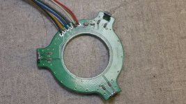
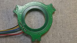
![Astro%20Flight%203220%20halls%201_zpsudtmojyz[1].jpg](/sphere/data/attachments/118/118746-010ce7be89fbcdd6a0e2f81835dafdc2.jpg)