Compact Field Oriented Controller, ASI + Grin, limited run

Well, we have 2 bikes here..one is my Mac, the other is a Crystalyte DD hub. I'm the mechanic in the household, so I get to fix things. Since getting the PRs was my idea- I REALLY get to fix things. I'm trying to figure out regen on the Crystalyte at the moment. The bike works fine without it..but I'd sure like to get it working. Hence the several questions....
I think I'm gonna save me a known good, working .xml file and then reflash from scratch tomorrow. I'm sure some of the fiddling around I've done has to have changed some things...Maybe starting from scratch will help. Then I can try what you mentioned again and see what happens. Thanks for the help ;)
Oh, and I was rotating the pedals by hand..had the bike up on jacks so it was safe to play with.
 
Well, whadda ya know..flashed back to stock with the quality control .xml that Justin posted a few posts back and then set my CA at starting regen at .50 volts minimum time .5 seconds and it works perfectly. I now have regen! Hey Cycborg, you might want to try flashng that .xml before you play with it again. Not sure what changed, but it surely did change. YAY-off for a test ride!
 
Feature request:

Last night I went for a ride. The motor would not turn over and I discovered that the 5V line to the hall sensors has broken. I had to cut the ride short.

I guess most of you are thinking "what did you expect?!".

Well actually I was expecting the motor to run (Sensorless).
I have been racing RC cars for many years before I started e-biking. Every RC controller that I know of, which supports both sensored motors and sensorless motors, will automatically run the motor sensorless if it doesn't detect the sensors.

This feature seems more important in e-biking than RC; Most people don't take on a ride a portable soldering iron to to fix broken wires nor a laptop to change the controller's setting to Sensorless. Fortunately I didn't get far in the woods so it wasn't a long pedal/push back to the trail head. It was however very frustrating to think that my controller IS capable of sensorless running yet it wouldn't run the motor.

In short, please make the controller switch to sensorless mode if it doesn't detect the sensors (or ask ASI for this feature?).

Thanks,
Avner.
 
ferret said:
Feature request:

Last night I went for a ride. The motor would not turn over and I discovered that the 5V line to the hall sensors has broken. I had to cut the ride short.

I guess most of you are thinking "what did you expect?!".

Well actually I was expecting the motor to run (Sensorless).
I have been racing RC cars for many years before I started e-biking. Every RC controller that I know of, which supports both sensored motors and sensorless motors, will automatically run the motor sensorless if it doesn't detect the sensors.

This feature seems more important in e-biking than RC; Most people don't take on a ride a portable soldering iron to to fix broken wires nor a laptop to change the controller's setting to Sensorless. Fortunately I didn't get far in the woods so it wasn't a long pedal/push back to the trail head. It was however very frustrating to think that my controller IS capable of sensorless running yet it wouldn't run the motor.

In short, please make the controller switch to sensorless mode if it doesn't detect the sensors (or ask ASI for this feature?).

Thanks,
Avner.

It should be in one of phaserunner's parameters.

I believe it's parameter #127 - Motor Features
Option 1 is Fault tolerant hall (switch to sensorless) - which should switch the controller to run sensorless if it doesn't detect / if there's faulty hall sensor.
 
UPDATE:

I found out that the Phase Runner Suite software can access parameters using the Dev Screen or the Edit->Edit Parameters drop down menu.
I tried adding parameter "Motor Features[01] Fault Tolerant Hall" and tried both checking and unchecking it. I also tried manually setting the value to 1 but none of these actions allowed the motor to run with the hall sensors disconnected.

Additional info:
When I check and uncheck Motor Features[01] I see the value change in parameter 127 between the values 16 and 8. In both cases I can hear the motor buzz and see phase and battery currents in the Dashboard screen, the motor doesn't move.
When the controller is in sensorless mode the motor does run, so I guess it is not a problem with the sensorless starting parameters.

Can anyone confirm that the Fault Tolerant Hall feature is working on their Phase Runner?


UPATE, ISSUE RESOLVED:

After consulting with Justin the problem was fixed by flashing the xml file he uploaded here:
https://endless-sphere.com/forums/viewtopic.php?f=31&t=65031&p=1310696&hilit=+file#p1310696


Avner.
 
justin_le said:
MBV said:
Hi Justin
How do i access the parameters in the ASI firmware?
You can install the bacdoor software just fine (links are both on our website and on this thread) and connect to the phaserunner that way, but be warned it's not very user friendly. Almost any parameter you see there can also be edited in the phaserunner suite software if you go edit->edit parameters. The exact details for setting up the "always engaged" mode I don't remember, this was from a discussion we had with ASI's engineers a few years ago and they said they had done that or were experimenting with it.
It would be wonderful if there is a setting controlling the RPM ramp up rate. I have also noted that when giving just a little bit of throttle you are in fact controlling the motor rpm. If one could increase that controllable RPM range it would also solve much of the problem.
The little bit of throttle is only varying the RPM indirectly, in that you do need a bit more torque to spin the motor fast compared to spinning it slowly so there is some adjustable range here. If we can't find an intrinsic solution with the PR itself, then one possibility would be to make the CA3 have a special start mode, where after applying throttle it would first set the throttle just above the min output for a fixed time (enough for the motor to speed up at very low torque and engage), and then after that let it ramp up properly and respond.

Are you currently using an ebrake to cutoff the motor power during the shift transitions, and if so do you have it hooked up to the CA3? One other possibility would be to set the brake output voltage to like 1.3V or something that commands just a low torque on the motor, then when you touch the brakes during shifting the motor won't cutout but will instead go to a very low torque mode where it won't impact the shifting but still stays engaged so that there is no slack.

Can I connect a wheel speedsensor to the phaserunner? That way I might be able to configure the motor to stay slightly engaged given that the wheels are moving? Or can I do the same with the CA3?

You could indeed also setup a PAS sensor with the CA3 and have the PAS watts be really low, like 20W or whatever it takes to spin the motor up, but have your PAS sensor signal coming from a speedo sensor on the wheel rather than the cranks. Then whenever the bike is moving there would be a small motor power to keep it engaged whether you have the throttle down or not.

Hi Justin

I installed the Bacdoor software but could not get the latest version running. I tried installing an older version and that version worked. Have not had time to try changeing any settings yet.

No I am not currenty using any ebrake sensors. They are on the to do list after I have managed to get the bike running smoothly.

I like the idea of being able to set a startmode on the ca3. Would it then be possible to make the ca3 to never drop below that same output voltage given that the wheel is spinning? And when the wheel comes to stop the throttle voltage would drop. I would like to be able to use the pedal assist sensor for pedal assist :)
 
I'm on the outlook for the next controller...

Given suitable heatsinking: what is the max continuous battery current phaserunner can handle?
 
Spongeworthy said:
vex_zg said:
I'm on the outlook for the next controller...

Given suitable heatsinking: what is the max continuous battery current phaserunner can handle?

From what Justin told me and other experiences from users on the forum, about 70A continuous phase amps. More info herehttps://endless-sphere.com/forums/viewtopic.php?f=3&t=82196

cool. If phaserunner with only 6 FETs can do 70A then most of other controllers could be suboptimally designed requiring 18 FETs to achieve 70A continous.

I wonder if one could make an "adapter" for the frame, a solid aluminum block with flat surface to mount phaserunner on one side and curved surface ideally matching a bike frame tube on other side, and then use the bike frame as a heatsink. Would this over time incurr some weak points in the bike frame.
 
vex_zg said:
most of other controllers could be suboptimally designed
One big factor here is synchronous rectification. Look it up if you want the details, but basically the low-side FETs of less sophisticated controllers conduct a lot of current through the body diode, rather than the usual drain-source channel. Since the body diode has a significant voltage drop, this means a lot of unneccesary heating. PhaseRunner and other advanced controllers coordinate the switching of the low- and high-side FETs to avoid this. If this isn't done carefully, you can have both FETs on at once, creating a short circuit across the battery straight through the controller. But the brain chips of these controllers do it pretty routinely.

Also, the PR's heatsinking is exceptionally well designed.
 
I personally own 3 phaserunners - 1 to drive my single wheel drive, and the other 2 to drive my 2WD. They're absolutely excellent (especially mounted on copper heatsinks), extremely reliable, and may I say weatherproof as well (to some extent.)

Now, if only Grin (*hint to Justin) would make 2 more versions of this - a larger version (say 12 fets) for more powerful builds, and a smaller even more compact version for say electric skateboards - to complete the lineup.
 
"Level 3 access" discussion:
I saw in few posts, that people who get strange behaviours can "reset" their Phaserunner by allowing level 3 access, and than uploading an .xml file which Justin uploaded. This indeed solves the problem, but creates two other problems: It doesn't really tell us what was wrong and how can we know if it happened again (we don't carry our laptops when we ride all the time), and secondly - it resets ALL the settings in the Phaserunner so you have to define all the values again.
I don't think this is a correct way to solve technical problems.

Can someone explain what are those level 3 access options, and how can they be directly accessed on the software when you enable them?
After enabling, I didn't see any more options on the main and advanced screens. I assume that more items appear under "Edit parameters" but as there are hundreds of them I am not going to count.
I do want to know how to solve problems rather than doing a "format" action. :D

For example, in my case, I have speed limit issues which has been solved by inputting a much higher speed limit (180kph) and a much smaller wheel diameter (15inch). It works, and I know I can "format", but I want to know what and where to fix.

If I ever get a fault when I am cycling in the middle of nowhere or a big field and I can't go-on since I have no laptop which can help me "format" or change a setting - This controller is not truly a FIELD oriented controller. :wink:
Here is a practical scenario: You lost one of the hall sensors, and the controller will refuse to work even though it's capable of being sensorless. It just waits you to plug the computer and change it's behaviour to "Sensorless". There is a setting, apparently, which can tell the controller to shift to sensorless operation if there is a hall failure but it's not enabled by default. This is just one example.

To conclude:
A field-oriented-controller should always keep going (albeit at reduced performance or features) unless certain thresholds are passed, such as LVC or temperature.
 
If you want it to be auto-sensorless this should be programmed and tested before there is a hall failure.

I would hope these parameters are not changing after programming. Like a computer BIOS, there are many settings, and not all of them are documented or even generally accessible. So resetting to a known good state and then explicitly setting only the parameters that need changing (and that are understood) is a valid and cost effective approach. After making the setting changes, a thorough testing process verifies that the system works the way it should, and no more settings are changed without a complete re-testing.

It would be nice if we could understand every parameter, but it is unlikely. Doing so would require intimate knowledge of the actual code inside the controller, and the electronics there. With the more complex controllers this requires professional level training and significant experience, and perhaps specialized tools and direct manufacturer's support. We did this kind of thing at work and it required a dedicated professional and a lot of hands-on work and time to get to that level, and there were still things that were not always understood, for which the factory support was used (and occasionally factory support didn't know either). The cost of this was quite high.
 
thunderstorm80 said:
Here is a practical scenario: You lost one of the hall sensors, and the controller will refuse to work even though it's capable of being sensorless. It just waits you to plug the computer and change it's behaviour to "Sensorless". There is a setting, apparently, which can tell the controller to shift to sensorless operation if there is a hall failure but it's not enabled by default.
Pretty sure the setting you want here is Motor Parameters -> Fault Tolerant Hall, so look for that under Edit Parameters and give it a try.
 
Jason3 said:
Overall I like where you're going with this :)

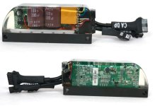
Well everyone, as it is last week we sold the very last Phaserunner that used the hardwired phase and battery leads with the built in on-off switch, and have fully switched over production to this design with the connectorized power leads. The actual assembly process is definitely a lot cleaner now, we can use prebent solid core wire wire for going into the powerboard PCB and don't have to handle the excess cable bundles during the various mold installation and potting steps
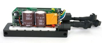
Connectorized Phaserunner Assembly.jpg

And after potting:
Side Views of Connectorized PR.jpg

However, as mentioned we loose the embedded on/off button since there wasn't room to fit the latching circuitry on the PCB with the real estate taken up by the XT60 and MT60 connectors on the daughterboard. So by default now all the controllers are similar to our first production batches from 2015 which have the on/off key switch wires tucked under the throttle heathrink. By default these are shorted together to the controller will just turn will turn on with battery power, and if you want to have a separate controller on/off switch you need to separate these wires and hook them up to a switch, illustrated in this post here
https://endless-sphere.com/forums/viewtopic.php?p=1075988#p1075988

For better of for worse, we stuck with JST-SM connectors for now on all the signal wires. There wasn't any really clean way of handling the motor phase cable. If you have separate phase cable and hall cable then you just terminate the phase with MT60 and halls with JST, but if it's a single cable that has both the phase and hall wires in one jacket, then this needs to be terminated with two plugs that are staggered at different distances, with the phase wires to MT60 being about 4-5cm longer than the hall plug.
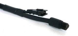
MT60 + JST Cable Harness Closeup.jpg

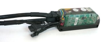
The net effect isn't too bad,
Connectorized Phaserunner Cables Attached.jpg
but it is a bit bulkier and messier than the previous design that just had a clean cable exit from the mold and so we'll be including a velcro sleeve with each PR device that you can wrap around this connector bundle to clean up the look on the bike frame.

For now we'll initially be including a phase cable that has a 1m lead to anderson powerpoles for the motor like this:
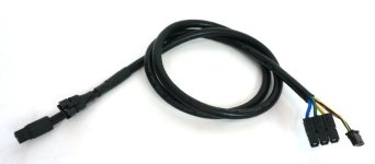
Connectorized Phaserunner Phase Cable.jpg

And the plan is to start the process of preparing an assortment of cable harness options that people can choose from to have setups that are plug and play with other existing motor connector standards. Like the Higo L1019 (http://www.higoconnector.com/products/l1019ag-p-00-az-1000/DK99K#title). If people have input on what kind of length and termination type would be handy for a lot of the builds out there which are getting Phaserunner upgrades, now's the time to chime in!

We still need to now make an updated user manual and all that so that the documentation reflects these design changes, but just know that any phaserunners ordered now will be of this type regardless of what the photos show on our website.
 
justin, please order and start shipping with these so that phaserunner can jump over the current power/thermal limitations.

New MOSFET is coming from infineon, Only 1.5mOhm resistance with Vds=100V, 300A continous current rating.

Some minor mech redesign might be needed for the different package but well worth it. There are other mosfets with same package for testing in the meantime.

cca 24 weeks lead time but well worth it.

https://endless-sphere.com/forums/viewtopic.php?f=30&t=90311&p=1316426#p1316426
 
What about going to something like the Higo panel-mount connectors for the exit of signal cables from the Phaserunner? Then there'd be no wires at all coming out of it, and the Higos are at least very water resistant if not fully waterproof.

I've not checked to see if there would be enough room, but if you used a PCB to solder the Higos to, they could be directly cast into the mold with the PR itself, so that they are supported by the cast resin as well as the PCB (because they take a bit of force to twist/pull off).
 
vex_zg said:
justin, please order and start shipping with these so that phaserunner can jump over the current power/thermal limitations.

New MOSFET is coming from infineon, Only 1.5mOhm resistance with Vds=100V, 300A continous current rating.

Some minor mech redesign might be needed for the different package but well worth it. There are other mosfets with same package for testing in the meantime.

cca 24 weeks lead time but well worth it.

https://endless-sphere.com/forums/viewtopic.php?f=30&t=90311&p=1316426#p1316426

This looks really promising! What's the specs / type of mosfets currently being used on the phaserunners?
 
Phase runner to PC not communicating.
I just had updated some parameters in my phase runner screens to emulate what another user had tried with the same motor and battery set-up (i.e 72 V battery running BBS HD mid drive), it turns out the parameters were not ok to save to the phase runner as the motor didn't run on a very short test. So after the bike motor didn't run, when I went to reconnect the usb port to the phase runner, it will not connect. I checked that the port was correct and even downloaded/read the settings from my cycle analyst so I know the cable is ok.

Is there a way to reboot or is it possible the controller has failed?

The cycle analyst connected shows everything is normal.

On my bike when I autotuned the phase runner didn't find the hall sensors, so I was running senso rless and changed the setting to Halls for start and sensorless running. The other user had been able to get the hall sensors to detect by auto tuning at 50V then updating the voltage.

I had tried to change the Kv value and a few other minor items I was at 12.65 rpm/V and the other user was at 43 rpm/V. I also adjusted a few other items to match his file.

After being off my bike for over 2 months having broken ribs from a ebike fall on a trail, I am disappointed that I can't get my bike running. Your support will be appreciated.

Regards

Colin
 
Phase runner LED codes for phase runner not working and unable to get com port to connect to restore or reset to last working set-up...

Appears to repeat over and over when 6-1-6-4 powered blinking LED with a longer pause after the "4". From the phase runner manual 1-6 could be Motor Hall sensor fault but there are no codes listed stating with 6 or 4?

However, turning the power on and off with switch doesn't reset the errors...

Any other things to try?

Regards

Colin
 
justin_le said:
And the plan is to start the process of preparing an assortment of cable harness options that people can choose from to have setups that are plug and play with other existing motor connector standards. Like the Higo L1019 (http://www.higoconnector.com/products/l1019ag-p-00-az-1000/DK99K#title). If people have input on what kind of length and termination type would be handy for a lot of the builds out there which are getting Phaserunner upgrades, now's the time to chime in!

That Higo connector is awesome

3 x 4mm² as phase leads
only 8,5mm diameter
IP67 protection

I have seen it once as a pair for 50 EUROs (the German CA dealer had it listed).
thats the price to pay for high quality stuff and it will safe a lot of time for soldering and crimping other connectors.

The integrated Amass connectors are nice, but it looks like the assemble process (soldering and routing the phase wires) is a pain in the ass.
A little bit longer case and PCB would make this part easier i think..
 
my 2 cents

This looks worse that the last model. It looks pregnant with connections and I had mine on my handle bars for maximum air flow. With that added stuff there it will be bulkier where ever you put it. With cables you got more chances to hide connections somewhere else.

file.php


My hunches are usually proven wrong by Justin, but for us that push the thermal limits of this gem, are we going to be increasing that thermal transfer to the connectors. The only thing that failed my on my phase runner all axle plug and play purchase was the Anderson connectors running high phase amps, something I didn't think was possible but if you need someone to test idiot proof then I'm your man.
 
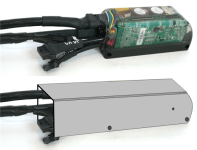
Most folks will still probably bolt this little guy up to the seat tube. In the same vein as the Grin Velcro sleeve, it would be pretty easy to fab a little three-sided metal or plastic shroud to make the PR appear longer but hide the connection complications. A long slim form factor might arguably be less attention-getting and 'electric' looking. Maybe something like this:

PrShroudedComparison.png
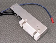
Here's the same shroud idea but with the PR lying on its side with a heatsink instead of a frame mount. This hangs centered under the rear luggage rack with the heatsink off to the left in the air flow under the rack. No connections are visible and when painted black, it's pretty tidy and unobtrusive.

PrUnderRackMount_unpainted_500.jpg
Anyhow, I'm not a fan of attached cables (or the former pushbutton on-off switch), so this new design looks pretty attractive. The earlier design put me pretty clearly out of the Grin target demographic, so I'm pretty happy that manufacturing considerations accidentally pushed my wish list items to the top.... :D
 
Back
Top