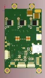
KT motor controllers -- Flexible OpenSource firmware for BMSBattery S/Kunteng KT motor controllers (0.25kW up to 5kW)

stancecoke said:
I've built a test bench for the comparison of the different working modes, to see how important the correction angle is in real life :)
I am being thinking in what I learned when developing the FOC firmware for the electric unicycle and try to adapt to this Kunteng STM8 controllers with much more limited hardware.

In FOC, the algorithm take as input the 2 phase currents and motor rotor position (from hall sensor for instance) and outputs 2 different current values: Id and Iq. On Kunteng STM8 controllers, there is only the signal of 1 phase current and it does not have processing power available to the FOC algorithm.

Id current is the current/torque we want to apply to the motor and so we control PWM duty_cycle value in a way to have the desired Id current in amps.
On Kunteng STM8 controllers, I think we can simple read the max value of the sinewave phase B current and multiply with a factor to have the average current value ----> Id current.

Iq current is a vector with 90º displacement compared to Id vector. Iq must be controlled to be 0 and so the motor will have max efficiency. To control Iq to be 0 we need to adjust the phase/angle voltage that we apply to the motor phase wires.
On Kunteng STM8 controllers, I think we need to find the offset/gap of the current sinewave compared to the motor rotor position (hall sensor signal). I need to find a working and robust algorithm to measure this offset/gap of the current sinewave!!! Any ideas??
 
Atmel has all the math here, and seems to have example code

https://www.google.se/url?sa=t&source=web&rct=j&url=http://www.atmel.com/Images/doc32126.pdf&ved=0ahUKEwiq8bSE-4XWAhVDJJoKHU-tCGoQFgglMAA&usg=AFQjCNEH5beYKwDGCuerD7YwO4GpvxPOkA
 
casainho said:
stancecoke said:
I tried an algorithm based on zero crossing and it always fails, going always in one direction -- have to take more time to verify/debug this algorithm.

I think you have to consider the gradient. If you detect a falling edge at the last zero crossing before the hall rising event, you have to shift in the one direction, if zero crossing with rising edge into the other direction...

regards
stancecoke
 
So I think I was able to figure out how to do FOC on the BMSBattery S06S/Kunteng STM8 motor controllers!! Due to the hardware limitations, I think FOC is only doable with losing much resolution but that should be enough for this application. But this way there is not need to do multiplications and calc sines and cosines, just read directly phase B current to have ID and IQ currents!! I write my notes, please see here: https://opensourceebikefirmware.bitbucket.io/Various--Endless-sphere.com_forum_messages--2017.09.02_-_How_to_do_FOC_on_the_BMSBattery_S06S-Kunteng_STM8_motor_controllers.html

If this is valid, I will simple try to implement FOC!!! :) :)
 
My suggestion:
Use every hall event (6 cases) to read in the phase current and calcutlate
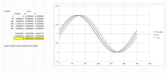
test = (i(120°)+i(180°)+i(240°))-(i(300°)+i(0°)+i(60))

if "test" is <0 (<127) then the current is after the rotor position, if "test" is >0 , then current is in front of rotor position. If "test" is Zero, rotor position and current are in phase.

file.php


Sinus.JPG

regards
stancecoke
 
stancecoke said:
My suggestion:
Use every hall event (6 cases) to read in the phase current and calcutlate
test = (i(120°)+i(180°)+i(240°))-(i(300°)+i(0°)+i(60))

if "test" is <0 (<127) then the current is after the rotor position, if "test" is >0 , then current is in front of rotor position. If "test" is Zero, rotor position and current are in phase.
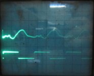
I am not sure, in fact, I now think that may be some bits missing... because the current phase is only a sinewave when the angle is perfect but most parts of times, when we want to correct it, it is not a sinewave... I saw with my oscilloscope the FFT (Fast Fourrier Transform) and clearly when out of phase it does have noise and other frequencies, so it is not a sinewave, we should not being looking for a sinewave. See here -- it is far from a sinewave and have a kind of long part with zero value so no clear zero crossing:
79-3.png


If the 3 phase currents were sinewaves, with the same amplitude and phased out 120º of each other, no point to read each of them... so reading only one, I don't know, some bits seems that are missing to me.

If at least the zero crossing happens always on the same position...

And with motor without load, the read current is so low:
79-5.png


At least one thing I know: on FOC, I had to heavy low pass filter ID and IQ values so I will need to filter also here.
 
OK, that't triky, indeed.

I've done first measurements with the test bench. It would be interesting, how the original Kunteng Firmware would behave...

index.php


regards
stancecoke
 
stancecoke said:
I've done first measurements with the test bench. It would be interesting, how the original Kunteng Firmware would behave...
GOOD!!

Yes, would be great to compare original. Why don't you buy some 2 spare units of S06S, I think they are not that expensive. With me, I have another S06S with original firmware that seems not working anymore and a S12S that I didn't even tested it.

So for the graphs we can see that with increased load on the motor, it asks more current than the most efficient controller (that uses FOC). Did the speed change?? So we know that angle phase out changes with increased current and increased speed and the results seems to show it.

005.png

Image taken from Shane Colton documentation.

Angle phase out changes with:
- I*R (current * winding resistance)
- I*w*L (current * velocity * winding inductance)
 
I think I found a way to correctly detect the zero crossing when the motor is running on the air and the phase B current the signal is very weak or when it is far from being a sinewave and the zero crossing takes also a long time:

https://opensourceebikefirmware.bitbucket.io/Various--Endless-sphere.com_forum_messages--2017.09.03.html
 
Ok, that is a kind of "low pass filtering", too, I think
You have read in the current permanently in this case. Wouln't that need to much processor-time?!

regards
stancecoke
 
I've soldered in the ACS712 now. You have to remove the solder bridge at the backside of the board.

index.php


In my first test with my oszilloscope I found less scatter and spikes in the current signal than I saw in your photos...
And I think I've used the wrong hall signal for triggering :wink:

Without Load.JPG


regards
stancecoke
 
stancecoke said:
Ok, that is a kind of "low pass filtering", too, I think
You have read in the current permanently in this case. Wouln't that need to much processor-time?!
My idea: read once every PWM cycle. Our resolution is 1 PWM cycle because we just can change the PWM duty_cycle every cycle of 64us so not big point to read faster than 1 PWM cycle.

I will make some testing firmware to verify If I can read the values correctly or there is noise/wrong values read... not easy as I can't send them by UART not the STM8 have and DAC to output the values.
 
stancecoke said:
I've soldered in the ACS712 now. You have to remove the solder bridge at the backside of the board.
GOOD!!!

stancecoke said:
Without Load.JPG
file.php
So it is not a sinewave... and without load that we will need to address. Do you think that low part is always under the 2.5V?? Would the algorithm I described work on this situation??
Was the motor running good or doing noise/vibrations?? I would say noise/vibrations because the top of the signal is not in phase with the hall sensor and also is a very out of shape sinewave.

stancecoke said:
With Load.JPG
file.php
Ok, almost perfect sinewave and seems to be in phase with hall sensor signal so the motor would be run the most efficient possible, right? The algorithm would work very well here and detecting not time/phase out compared to the hall sensor signal and so not need to adjust the angle.

Can you please try run your motor at max speed and see if you can change the angle by UART and have a good sinewave phase B current signal??
 
casainho said:
Was the motor running good or doing noise/vibrations??

The motor ran quietly...

casainho said:
Ok, almost perfect sinewave and seems to be in phase with hall sensor signal so the motor would be run the most efficient possible, right?

Hmm, not really perfect sinewave, especially in the negative half wave. Efficiency is not as good as the Lishui FOC at this working point.

Oszi with sinewave.JPG

even with no load, the first half wave looks good, just a little late, the second half is poor...


I've taken another photo at "full load" (4,5A @ 36V on motor) triggered by the right hall sensor. Phase angle seems to be OK, but efficiency is not OK....
But I've not tried to adjust the angle to an optimum at full load manually yet.

file.php


regards
stancecoke
 
stancecoke said:
casainho said:
Was the motor running good or doing noise/vibrations??
The motor ran quietly...
casainho said:
Ok, almost perfect sinewave and seems to be in phase with hall sensor signal so the motor would be run the most efficient possible, right?

Hmm, not really perfect sinewave, especially in the negative half wave. Efficiency is not as good as the Lishui FOC at this working point.

even with no load, the first half wave looks good, just a little late, the second half is poor...

I've taken another photo at "full load" (4,5A @ 36V on motor) triggered by the right hall sensor. Phase angle seems to be OK, but efficiency is not OK....
Great work you are doing!!! Seems will be difficult to find an algorithm as the wave is really different from a sinewave :-(

stancecoke said:
But I've not tried to adjust the angle to an optimum at full load manually yet.
Please try. The automatic algorithm will not do better than what we can get on this manually tunning so with this test we can find the best we can get.
 
I've uploaded a new branch "PhaseCurrentExperimenting" to github.
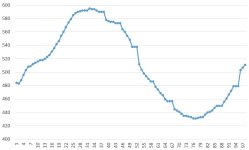
If you send "2" via UART to the controller, one electric revolution is logged
If you send "3" via UART, the logged data is printed to UART with the length of data at the first line.

If ADC is busy due to readThrottle from the main.c the last value is copied. You can see these phases quite clearly at the graph. So perhaps we have to improve the ADC Process for reading Throttle, Voltage and Battery Current....

Waveform PhaseBCurrent.JPG

edit: improved code a little to avoid calling of readThrottle while logging

and again I learn that I can't use git properly, both branches were updated.....

regards
stancecoke
 
stancecoke said:
I've uploaded a new branch "PhaseCurrentExperimenting" to github.
Great to have you also working on the motor control!! Together we should advance way faster!! And I bet the other parts needed to finish the firmware are way more linear/simple.

So, with your latest test you did what I wanted to do: testing reading ADC values on all points and see if any fail due to PWM noise (as we can see on my oscilloscope images, there is a lot of noise). Seems that all measures are correct and as explained on the literature: read on the PWM interrupt/middle of the cycle should not have noise as the noise should happen only with the PWM transitions and not during the time of the PWM cycle.

stancecoke said:
If ADC is busy due to readThrottle from the main.c the last value is copied. You can see these phases quite clearly at the graph. So perhaps we have to improve the ADC Process for reading Throttle, Voltage and Battery Current....

edit: improved code a little to avoid calling of readThrottle while logging
Great, I want to see your solution!!

stancecoke said:
and again I learn that I can't use git properly, both branches were updated.....
Don't worry and I hope by now you could see already the value on using git and that you took advantage of it.

By the way, what is your background? electronics? firmware?
 
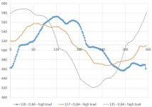
I've done two test:

- running motor with (around) 0,8A@36V with "high" load, varied the correction angle manually from 120 to 135
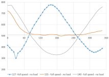
- running motor at full speed with no load, varied the correction angle manually from 127 to 140

It seems to do the "autotuning" with load should be much easier. We can search the zero crossing at 180°, that seems to be the most stable condition.
0.8A-high_load.JPG

At high speed with no load, I have no idea yet, I think we have to take more logs first, to find a suitable approach.
full_speed-no_load.JPG

casainho said:
By the way, what is your background? electronics? firmware?
I'm a mechanical engineer, electronics is just a hobby... :wink:

Regards
stancecoke
 
I did the code to read the IQ current, is simple and seems to be working. I tested with my slow eRPM motor, with low, medium and max speeds (with power supply at 24V) and the motor was most efficient when IQ value was near zero - the motor was quieter and the power supply did show the lowest current value. I also verified that measured IQ value was near the rate increased value I saw on my lad power supply, when I moved the position_correction_value to wrong values.
At lowest speed (like just after startup the motor when angle interpolation is not running yet) the measurement of IQ current also seems to work ok as also the effect of changing position_correction_value.

I also verified that at higher speeds, a small change of position_correction_value have a high impact on IQ current/motor efficiency.

Code used to measure the ADC IQ current value and do a low pass filter:

Code:
switch (hall_sensors)
{
  case 3:
(...)

  if (ui8_adc_read_throttle_busy == 0)
  {
    ui16_ADC_iq_current = ADC1_GetConversionValue ();
    ui16_ADC_iq_current_accumulated -= ui16_ADC_iq_current_accumulated >> 3;
    ui16_ADC_iq_current_accumulated += ui16_ADC_iq_current;
    ui16_ADC_iq_current_filtered = ui16_ADC_iq_current_accumulated >> 3;
  }

And then the filtered value was printing with this code:

Code:
// Phase current: max of +-15.5 amps
// 512 --> 15.5 amps
// 1 ADC increment --> 0.030A
// RMS value --> max value * 0.707
#define ADC_PHASE_B_CURRENT_FACTOR_MA 21 // 0,030273437 * 1000 * 0.707

ui16_temp = (ui16_ADC_iq_current_filtered - 511) * ADC_PHASE_B_CURRENT_FACTOR_MA;
printf("%d, %d, %d\n", ui16_motor_speed_erps, ui16_temp, ui8_position_correction_value);


On the next images, you can see how the motor speed eRPM changes (speed can increase a bit, equivalent of field-weakening?) and IQ current change while I was manually incrementing/decrementing the position_correction_value. The motor was most efficient when IQ value was near zero, as expected.
Conclusion
• the low resolution FOC algorithm need to look at IQ current and increment/decrement position_correction_value until IQ current is near zero.

eRPM: 29


eRPM: 48


eRPM: 60 (max speed)
 
stancecoke said:
casainho said:
By the way, what is your background? electronics? firmware?
I'm a mechanical engineer, electronics is just a hobby... :wink:
Then you should be very proud!!

KingQueenWong said:
casainho - Software Engineer;
stancecoke - Mechanical Engineer;
I am a Electronical Engineer.
:mrgreen:
I am a electronical enginner also, with my most experience in firmware but looking to jump to software development because in Portugal, almost no company do product development that includes develop a physical product that have electronics and firmware (this are developed in China) but there are many developing software. Also firmware is more and more high level/software due to low cost processors and increased complexity.
 
casainho said:
Conclusion
• the low resolution FOC algorithm need to look at IQ current and increment/decrement position_correction_value until IQ current is near zero.
I did a quick code and it seems to work but I wasn't able to fully test it because of the transition from startup to sinewave using interpolation..... :(

Running on main():
Code:
if (ui16_motor_speed_erps > 7)
{
  if (ui16_ADC_iq_current_filtered > 512)
  {
    ui8_position_correction_value++;
  }
  else if (ui16_ADC_iq_current_filtered < 504)
  {
    ui8_position_correction_value--;
  }
}
 
Back
Top