Alan B said:
Let's take a look at various current levels and see how much heat is generated in the FETs of an actual controller.
Some AOT290L Specs:
Drain Current Max 140A (110A at 100C) continuous
Max drain resistance 3.5 mOhms at 25C (5.7 at 125C)
Diode forward voltage max 1V (at 20 amps)
Calculations
The calculations are fairly simple: I squared times R for heat generated in the FET by current when the FET is on. When the FET is off the heat is zero (unless current is flowing in the body diode, see below). During the transition between states the power dissipated is large, but the time is so short (in a good design) that the heat generated is small compared to the conduction heat at high current.
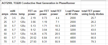
This current is passing through two of the FETs. (Actually it is passing through one fully, and divided between two others as the vector rotates, but to keep it simple we'll call it two for now). So we multiply by two to get total conductive heat in the heatsink. The following table shows this for 25 amps at 25C, and for 25 to 70 amps at 125C.
FOC Controllers like the PhaseRunner use "synchronous rectification" where they turn on all the FETs involved in conduction rather than allowing some of them to operate in the "diode" mode. The control algorithms and timing are more complex with synchronous rectification so it takes more CPU power and more software.
For controllers that use the inherent body diode, the power dissipation is E * I, or current times 1 volt, the forward diode voltage drop. I don't know if the PowerVelocity is doing this, but most trapezoidal controllers do. In this case the above calculation of heat applies to only one FET, the other uses the current times voltage drop calculation, which would be from 25 to 70 watts in this case, more power dissipated in the diode conduction mode than in the FET on state.
As you can see in the table below, the heat in the FETs and heatsink is very low even at 40 amps. Above 40 amps it begins become more significant due to the squared term in the equation. However this is well above 3000 watts in the load. Users have reported being able to run the PhaseRunner at the 5KW level with a sufficiently large heatsink, at least for some modest period of time.
I added the right hand column to the table below to show what happens in the common controllers that use the body diode to handle the current. This results in a significant increase in heat production, especially at modest currents.
In Conclusion
The heat generated in the FETs has nothing to do with the FET's Power Dissipation rating. FET heat is produced primarily by current flow through the FET and the resistance of the FET. The system voltage has little to do with FET heating. When the FET sees full voltage it is turned off and there is no current flow or heat. The system voltage has a lot to do with power delivered to the load. To get the most power through a PhaseRunner requires operating toward the higher voltages and using a motor that uses the voltage with lower current (often called torque type motors). A so called "speed" winding that uses lower voltage and higher currents will not be able to get as much power from a PhaseRunner, or any controller with modest current capability. For those you'll want to use a high current controller. Choose the motor to match the controller for best results.
Observation
The same capability should apply to the six FET PowerVelocity controller if they drive the FETs as well and if they avoid using the body diode of the second FET. If they use the body diode, then the ratings of the 12 FET model would be approximately equivalent to the 6 FET PhaseRunner due to the extra heat generated in the body diodes. That may be why we see the somewhat similar capability of the 12 FET PV vs the 6 FET PhaseRunner, but I don't know for certain how the PV controller handles the FETs.
Thank you posting this! Very interesting stuff. Some I've read before and some I haven't. For example the body diode bit is new information. I assumed it was there to protect the mosfet from bEMF spikes like how you put a reverse biased diode across a relay coil. I'm guessing it can serve dual roles in that case. It sounds like using the diode is a bit of a cheat or rather poor timing in the MCU. Is there an article about this specifically that you can recommend?
I have no idea how the 3232 MCU handles the transition states. I have 3 o-scopes. I suppose if I connect probes to the various mosfet gates in the H-bridges, I'll see some interesting wave forms. What should I look for to determine if the body diode is used or not? Let's prove this thing out! What a great opportunity to learn something I haven't messed with before.
Regarding that 5kw you mentioned. Is that phase watts? I can't imagine how it could be anything else. There is a point where exceeding certain limits is just magical nonsense. 5kw split among 4 mosfets is 1250 watts each or 2.5X more than their rated wattage. This seems highly unlikely.
By "transition dissipated power",are you referring to the mosfet shutting down and as a result its increased resistance from source to drain? This would build up a good bit of heat for a short period of time. Of course fast mosfets such as the AOT290 are going to go from conducting to not conducting much faster than say the IRF4110. So by it's very nature the AOT290 on the same MCU is going to run cooler for that reason alone vs IRF4110's. Never mind that the Rds is a bit lower as well.
I have a ASI BAC2000 controller. It uses the same MCU as the phaserunner and is a 12 fet controller that uses the AOT290. Based on that 5kw you mentioned (To be honest, it sounds like absolute nonsense to me), then my BAC2000 is really capable of 10kw (More nonsense in my mind). It wouldn't be hard to implement my BAC2000 on my Currie scooter. It currently is running a 12 fet PV with AOT290's. This would be similar to my scenario with a trapezoidal and FOC controller, except it would be a basic FOC controller vs an excellent FOC controller. This my kind of challenge. The battery pack is capable of 100 amps continuous at 66 volts so there will be no problems with power delivery. I'm really curious to see how that works out! Right now I'm operating in 100% disbelief that I will see more than a small improvement. The motor is an 80kv C80100 which according to Alien Power is rated for 7kw. That too is laughable nonsense to me. Most 80mm outrunners with the same height stator stack are more like 4800 watts so I'm skeptical of that 7kw. But if what you say is true, then the first thing I'm going to notice is a large increase in motor torque. I will report my findings as I get the controller swap out going in my BAC2000 review thread. Right now that scooter has seen a single 6 mile ride and a couple of really short rides. I haven't tuned the controller settings beyond going with what will definitely work. I'm sure I can turn up the phase and battery amps more. That 6 mile ride got the controller just a little warmer than air temperature. We will see! I have no problem with being wrong.
What were you referring to "torque type motors"? At first I thought you were referring to motor Kv, but I don't think that's the case.
You've mentioned mosfet heat several times in various posts. Since the AOT290 switches states quickly and has a low Rds is will build up less heat regardless how it's used. However electronics all have limits. Super cool the mosfet to 0 kelvin and it's still not going to conduct 500 amps even if it's legs could handle it. Heat is not the only factor in junction failure. It's a good one no doubt! But every transistor junction has it's limits where it just melts down. If you could put a perfect heat sink at O kelvin on the mosfet, it's junctions would fail never the less at something like...I don't know 160 amps.
This brings me to something else. The TO-220 package. The 3 legs on anything in this package are .77mm x .48mm in cross section. This is a very tiny conductor for much amperage to flow through. It would be brilliant if that was the case because all my phase wires would be made of 20 awg wire. It's just not realistic to assume that those spindly legs are going to conduct 50 amps, never mind 140 amps. They would be glowing red hot in a second if they did. Why do I bother with 10 awg phase wires and 5.5mm bullets, when 20 awg wire and a 2mm bullet would be overkill? 20 awg is about 2X the cross sectional area of a TO-220 leg. Realistically, The TO-220 package in a 500 watt mosfet is going to see at 48 volts more like 10 amps and the legs can handle that just fine.

")