KT motor controllers -- Flexible OpenSource firmware for BMSBattery S/Kunteng KT motor controllers (0.25kW up to 5kW)

stancecoke said:
The controllers from aliexpress arrived today. On one hand I'm a little sad, they are no Kunteng KT-36.
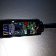
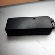
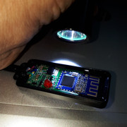
I now found some more information. This page from the netherlands says, that the µC is used in the old KU63 controllers.

He has some interesting links how to drive a BLDC on his page, also:

https://www.renesas.com/en-eu/doc/DocumentServer/026/U19166EE1V0AN00.pdf
https://www.renesas.com/en-eu/doc/DocumentServer/025/U18774EJ1V0AN00.pdf

And he refers to our project :)

I wonder how this could work, as the pinouts of the µCs are totally different...
Open source smart ebike controller with the KU63

By replacing the motor controller CPU by another CPU, the software can be customized. See here how the KU63 motor controller is used as base for an open source ebike smart controller:

stancecoke said:
I'll search for some more information and will try the "programming"
I still don't know, if there is any possibility to set some parameters via UART. I was not successful yet.

The efficiency of this controller is quite poor...

index.php


Regards
stancecoke
 
stancecoke said:
I am being in talk with him, since a few years ago when I tried to use KU63 -- he did the schematic and that was really important!!

stancecoke said:
The efficiency of this controller is quite poor...
No FOC, just 6 steps. Probably the same efficiency as S06P!!
 
casainho said:
No FOC, just 6 steps. Probably the same efficiency as S06P!!

It's sinewave, but with no FOC obviously.
I can't identify a phase current sensor on the circuitboard...

Regards
stancecoke
 
Regen does work, I was able to limit the regen current -- it is the same way as controlling motor max current but regen current is negative, as expected because current flows in the contrary direction.

While controlling motor max current we need to lower duty_cycle, to limit regen we need to increase duty_cycle, as regen increases when the duty_cycle is lower than the BEMF equal duty_cycle value.

But I still have some other issues with the motor code and so I could not yet commit my code.
 
That sounds good! I'm looking forward to test your code. I can use the regen with my testbench on the generator side :)

regards
stancecoke
 
stancecoke said:
That sounds good! I'm looking forward to test you code. I can use the regen with my testbench on the generator side :)
I am away from home, will take about 5 days until touch again on the firmware. My presentation went ok but not much users really interested. But there was a very good talk about a guy that have a company working as a consultant for startups that want to produce in China -- very good content, was great and let's see if I can learn and take some advantage for this project (not that I am looking to hardware production, but learning Shenzen and China culture is important).

You can look at the commit code I did specifically to add the regen current control: https://github.com/OpenSource-EBike-firmware/BMSBattery_S_controllers_firmware/commit/a04ef5e7eb0c5f95860ccf80dcf204ad0ba48708
 
stancecoke said:
Is your paper available for download somewhere?
Here: https://github.com/OpenSource-EBike-firmware/BMSBattery_S_controllers_firmware/raw/master/tools/pixelcamps_2017_presentation.pptx
 
I've just added an new branch with a first try for Display Support. I own a Kingmeter J-LCD only, so I added this. I've not tryed it in hardware yet.

Regards
stancecoke
 
stancecoke said:
I've just added an new branch with a first try for Display Support. I own a Kingmeter J-LCD only, so I added this. I've not tryed it in hardware yet.
That is great!!
I am being slowly returning after a pause of 1 week. I found some issues in the way I drive the motor, there is something that works but I don't understand why: how to drive the motor backwards but keep always increasing the ui8_interpolation_angle. I saw other firmwares that just change the values of two fases, like physically changing 2 phase wires to invert motor direction -- and this don't work and I wonder why.

About the LCD, I saw on web that Kingmeter J-LCD have the same wires/physical interface as Kunteng LCD. Does your implementation also follow the Kunteng LCD protocol?
 
casainho said:
I saw on web that Kingmeter J-LCD have the same wires/physical interface as Kunteng LCD. Does your implementation also follow the Kunteng LCD protocol?
No, the pinout is the same, but the protocoll is different. It should be easy for somebody who owns a Kunteng to implement and test the Kunteng protocoll....

Regards
stancecoke
 
stancecoke said:
casainho said:
I saw on web that Kingmeter J-LCD have the same wires/physical interface as Kunteng LCD. Does your implementation also follow the Kunteng LCD protocol?
No, the pinout is the same, but the protocoll is different. It should be easy for somebody who owns a Kunteng to implement and test the Kunteng protocoll....
Ok. I think Kunteng LCD seems the natural way to go for the ones that buy Kunteng controllers, because they pair with the controller with the original firmware and also seems that are the cheaper LCD on the market. So I think Kunteng LCD is a priority. Maybe you should buy one ;)
 
hey guys, especially casainho (the OP)

I've been following this thread off and on but it is too technical for me. I've been following because I have a KT controller and the KT-LCD3 display. What I'm curious about is whether you will be able to change the LCD3 so that it can display amp hours (Ah) and keep a running total until you reset it? (like a Cycle Analyst) If it could be displayed in the watt meter section maybe alternating displaying Watts and Ah (like those inexpensive Turnigy-type amm/watt meters) would be cool.

Also, I have a SW900/Kingmeter display with the 5 pin JST connector and confirm that it does not work with a KT controller. I've read that it uses a different protocol too. Cheers
 
rote said:
hey guys, especially casainho (the OP)

I've been following this thread off and on but it is too technical for me. I've been following because I have a KT controller and the KT-LCD3 display. What I'm curious about is whether you will be able to change the LCD3 so that it can display amp hours (Ah) and keep a running total until you reset it? (like a Cycle Analyst) If it could be displayed in the watt meter section maybe alternating displaying Watts and Ah (like those inexpensive Turnigy-type amm/watt meters) would be cool.

Also, I have a SW900/Kingmeter display with the 5 pin JST connector and confirm that it does not work with a KT controller. I've read that it uses a different protocol too. Cheers
I have no experience with that controllers you refer. Can you please elaborate more on the running total?? Is it reset after the end of trip or not?

The LCD is also programable because it have the same STM8 but fixed symbols on the display... but it is not a priority, at least for me, to change the LCD. Maybe better would be to adopt some cheap generic graphical LCD from Arduino would - than we would have all the flexibility.

Thank you.
 
FYI Kunteng recently issued a bluetooth adapter which plugs into the controller instead of the usual LCD3

http://www.szktdz.com/en/news_show.php?article_id=485

I managed to get a hold of one factory sample.

So perhaps you can only implement this KT or CA protocol, and use one of the android apps for display.
 
vex_zg said:
FYI Kunteng recently issued a bluetooth adapter which plugs into the controller instead of the usual LCD3

http://www.szktdz.com/en/news_show.php?article_id=485

I managed to get a hold of one factory sample.

So perhaps you can only implement this KT or CA protocol, and use one of the android apps for display.
BMSBattery told me they only sell one S09 controller with the module, they don't seel the module at unit, so, the only option I have is to build my own module aince I believe may be the Arduino UART Bluetooth module + power supply.

Can you please open your module and take some pictures?? That would help a lot for us to be able to build, at least until shops like BMSBattery don't sell them at unit. Thank you.
 
Hmmm, after three days of testing the display communication without success, I'm quite helpless now. I have problems to read in the bytes from the display properly. I think it's a problem with timing. The reading "UART2_ReceiveData8();" seems not to be buffered, if you put this command at the wrong time you get complete rubbish....

regards
stancecoke
 
stancecoke said:
Hmmm, after three days of testing the display communication without success, I'm quite helpless now. I have problems to read in the bytes from the display properly. I think it's a problem with timing. The reading "UART2_ReceiveData8();" seems not to be buffered, if you put this command at the wrong time you get complete rubbish....
Can you confirm that you can "write" with success to the LCD? Any video?
 
stancecoke said:
Hmmm, after three days of testing the display communication without success, I'm quite helpless now. I have problems to read in the bytes from the display properly. I think it's a problem with timing. The reading "UART2_ReceiveData8();" seems not to be buffered, if you put this command at the wrong time you get complete rubbish....
UART2 that is used have interrupts for transmitting and receiving. If you need fast/real time processing, go and use the receiving interrupt!! Please see the example code: STM8S_StdPeriph_Lib/Project/STM8S_StdPeriph_Examples/UART1/UART1_Interrupt/stm8s_it.c

22.2 - UART main features
6 interrupt sources with flags
– Transmit data register empty
– Transmission complete
– Receive data register full
– Idle line received
– Overrun error
– Framing error or noise flag
2 interrupt vectors
– Transmitter interrupt
– Receiver interrupt when register is full

Code:
/**
  * @brief  UART3 RX interrupt routine.
  * @param None
  * @retval
  * None
  */
 INTERRUPT_HANDLER(UART3_RX_IRQHandler, 21)
{
    /* Read one byte from the receive data register */
    RxBuffer2[IncrementVar_RxCounter2()] = UART3_ReceiveData8();

    if (GetVar_RxCounter2() == GetVar_NbrOfDataToRead2())
    {
        /* Disable the UART1 Receive interrupt */
        UART3_ITConfig(UART3_IT_RXNE_OR, DISABLE);
    }
}
 
casainho said:
Can you confirm that you can "write" with success to the LCD? Any video?

as long as the reading does't work, it makes no sense to send something to the display....
UART2 that is used have interrupts for transmitting and receiving.

casainho said:
UART2 that is used have interrupts for transmitting and receiving.

Ok, I don't now the syntax to configure UART2 for interrupts. But that might solve the problem. As it is written here, you have to catch some possible errors, too. I'm too frustrated to read through tons of literature at the moment... :shock:

regards
stancecoke
 
stancecoke said:
Ok, I don't now the syntax to configure UART2 for interrupts. But that might solve the problem. As it is written here, you have to catch some possible errors, too. I'm too frustrated to read through tons of literature at the moment... :shock:
Take a break :)

And let's see If I can help you:

Initialization:

Code:
static void UART_Config(void)
{
  UART2_DeInit();

  UART2_Init((uint32_t)9600, UART2_WORDLENGTH_8D, UART2_STOPBITS_1, UART2_PARITY_NO,
                UART2_MODE_TXRX_ENABLE);

  UART2_ITConfig(UART2_IT_RXNE_OR, ENABLE);
    
  enableInterrupts();    
}
That was taken from the example code. I think should be easy for you to understand -- the news here is enabling the UART2_IT_RXNE_OR interrupt (Receive/Overrun interrupt).

And now the interrupt code, that you can use because you already did code for PAS interrupt, etc:
Code:
INTERRUPT_HANDLER(UART2_RX_IRQHandler, 21)
{
   /* Read one byte from the receive data register */
   readed_byte = UART2_ReceiveData8();
   
   - put readed_byte on a buffer
   - if readed_byte_number == packet_size (Kunteng LCD is 13 bytes)
   {
     - flag_processing_LCC_data = 1;
     - readed_byte_number = 0;
   }
}
The idea is to read every byte an put on a buffer. But we should syncronize/find the start of a packet... on Kunteng, seems that last (or maybe we can consider to be the start package, depends on perspective :)) 2 bytes are always "50 14" (e.g: 12 0 149 160 41 102 18 74 4 20 0 50 14). I would read them in sequence and then reset the readed_byte_number, knowing that next byte will be the 1st of the next package. In the end, the full package need to be verified against the CRC value.
 
casainho said:
vex_zg said:
FYI Kunteng recently issued a bluetooth adapter which plugs into the controller instead of the usual LCD3

http://www.szktdz.com/en/news_show.php?article_id=485

I managed to get a hold of one factory sample.

So perhaps you can only implement this KT or CA protocol, and use one of the android apps for display.
BMSBattery told me they only sell one S09 controller with the module, they don't seel the module at unit, so, the only option I have is to build my own module aince I believe may be the Arduino UART Bluetooth module + power supply.

Can you please open your module and take some pictures?? That would help a lot for us to be able to build, at least until shops like BMSBattery don't sell them at unit. Thank you.


The markings on the chip are
CC2540
F256
TI65J
P123 G4

If the lack of BT module is a blocker to your work I can consider borrowing you this sample.
 
vex_zg said:
The markings on the chip are
CC2540
F256
TI65J
P123 G4

If the lack of BT module is a blocker to your work I can consider borrowing you this sample.
Thank you. Can ypu please take the pictures with day light and maybe see if you can use the macro option on your mobile phone? And pictures also from the back side? Is more for documentation as seems to me that blue board must be the UART Bluetooth module, that transistors maybe to do voltage level shifting and and that big one is a voltage regulator. I will look at the LCD board and take pictures also. The LCD power circuit may be similar and I may use that to build my module.

My focus is the motor controller code and not the bluetooth and mobile app, that will be some day but not now :)
 
casainho said:
vex_zg said:
The markings on the chip are
CC2540
F256
TI65J
P123 G4

If the lack of BT module is a blocker to your work I can consider borrowing you this sample.
Thank you. Can ypu please take the pictures with day light and maybe see if you can use the macro option on your mobile phone? And pictures also from the back side? Is more for documentation as seems to me that blue board must be the UART Bluetooth module, that transistors maybe to do voltage level shifting and and that big one is a voltage regulator. I will look at the LCD board and take pictures also. The LCD power circuit may be similar and I may use that to build my module.

My focus is the motor controller code and not the bluetooth and mobile app, that will be some day but not now :)

I need to borrow a phone with macro, mine doesn't have it. Will do it soon.

In the meantime:
I asked the seller who sold me this bluetooth module if he can get more. He might be able to get some from the KT factory. Is anybody interested? I only asked because somebody here wrote BT modules can't be purchased separately.
 
vex_zg said:
In the meantime:
I asked the seller who sold me this bluetooth module if he can get more. He might be able to get some from the KT factory. Is anybody interested? I only asked because somebody here wrote BT modules can't be purchased separately.
I would like to buy 3 units of this module.
 
Back
Top