Micro Lebowski Controller - DIY 3kw

Quick update, Temp sensor will go on top of the PCB at Phase C, I will only place one as all phases will be similar and that's less traces running across the board picking up noise.

I have made the board wider 69.5mm and will incorporate the Driver stage on the right side of this board, so this will become a two-stack controller (driver and powerstage on the lower board, CPU on the upper, connection will be the same as before with 10-pin headers.
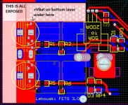
single_phase.PNG
 
how does this R5, R6 and D3, RP4 work ? Looking at the PCB, D3 and RP4 are not in the gate line but to the source. So you only have R5 or R6 as gate resistor ? Don't you want to use a diode to have different effective gate resistance for rising and falling edge ? (to make equal length miller plateaus for switch on and switch off).

Also, the output of the current sensor is very close to the high battery voltage (with all its spikes etc etc). Maybe a bit more distance or place a (red, coming from the low voltage) ground trace in-between the current sensor output and the positive battery ?
 
those components are as per the Infineon datasheet for their SMT chips.. If I use IRS2186 layout as per your schematic, I would leave D3 and RP4 unpopulated, and 0R across R5 and R6, but I think I like the idea of a gate resistor for each FET and close to the FET... so would need to play with the values and reduce the gate resistor on the original circuit. It was more a thought of,
well if it's good enough to stick in an application note for arbitrary driver circuits to connect to... it's good enough for me.

Good idea about squeezing the +Bat near the high-side FETs and placing a ground plane around the current sensor pins.. I could possibly bring the High and Low FETs closer together, move the Current sensor out from between them and rotate it clockwise 90 degrees... to get the Current sensor pins well away from everything. but that adds board width,

Anyway. bed time.
 
The controller runs a Bafang BBS02. I blew the factory controller after an impact must have shorted something to the case.

Anyways video here: [youtube]FVeoqoZloHo[/youtube] start at around 3:30 for lebowski test.

Note, I set the ERPM to 10k, then 20k, then 30k, and each time when hitting the ERPM limit it ran "rough" until I set it high enough that it reached it's max electrical speed at the 50V...

just an observation.

Andy
 
In the older version you have (was changed somewhere around 2.90) the erpm limiter was really only there to protect the motor from mechanically disintrigrating at high speed (ever seen those videos where they explode CD's that way ?) . Especially with field weakening speeds can become extremely high, so some sort of protection is necessary. The older style erpm limiting just shuts down the throttle when the limit is reached, the newer versions have a gentle ramping down of the throttle as the speed limit is approached...
 
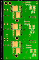
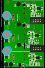
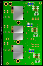
Some progress... very long time coming.
Nano Lebowski Controller - 150 phase Amps

BotLayer_Render (Custom).PNGTopLayer_Render (Custom).PNGBotLayer_Render_components (Custom).PNG

View attachment Nano Lebowski PCB Layers.pdf

My renders don't show it, but there are exposed sections of +Bat and -Bat on the top and bottom layers respectively, running alongside the Capacitors. This was a downfall of my previous layout that didn't leave space for a strip of copper wire and solder for the high-current path

This layout uses SMT FETs rated at 230A, similar to those used in the recent release of any number of tab welders. easy to mount to a case for heat sinking, and no isolation issues.

The biggest win for size is the new current sensors, surface mount capable of 150A, and 100A continuous. (with hugemongous copper track work.) my tracks are not as wide as in the tech note, but they will be thicker...

I've also re-routed the CPU board, to fit on top of this one, same layout, but with added temperature sensor. And I have decided to use pre-built 75 - 15V DCDC converter 15W. They are $38 AUD but I figured by the time I bought all the components and soldered them all up, my $38 would be gone, and these are proven devices. SImilaryl from 15V to 5V I use another retail DCDC converter, 5W.

One day I will get around to buying the parts, and circuit boards, and building one or two...
 
Has anyone done a board layout for the mosfets that takes to-220's and 18 or 24 mosfets?

I would like to build this thing and run at much higher wattage than 6 fets will get me.
 
Zombiess had done a 18 or 24 FET modular type layout..
The issue is current sensors.. this design uses current sensors for each phase. These ones that I am using (going to use) are treated to 150A so that is my max phase current. I'm just trying to make it as compact as possible.
 
Animalector said:
Zombiess had done a 18 or 24 FET modular type layout..
The issue is current sensors.. this design uses current sensors for each phase. These ones that I am using (going to use) are treated to 150A so that is my max phase current. I'm just trying to make it as compact as possible.

Thanks...I'll look around for more amperage, but I have 3 of them that are 200 amps each.
 
These are 200 amps.

http://www.ebay.com/itm/ACS758ECB-200B-SENSOR-CURRENT-HALL-200A-AC-DC/291921522537?ssPageName=STRK%3AMEBIDX%3AIT&_trksid=p2057872.m2749.l2649

I'm building a test unit. It will have one of these in each phase and a meter to read the output voltage of the hall. The meter will read voltage which with some very basic math can be converted into amps. I will be using them to build a phase current meter.
 
izeman said:
those are fine. i use them as well.
and if 150A phase is ok, then you're fine with 6x IRFP4468. they don't even get warm in my controller doing 3kW and 150A phase.

EDIT: Don't know why I originally said 6kw. Probably because I was talking someone else about an 18 fet, 6kw controller.

6 of the irf4468 ought to get you 4kw+++, not 3kw. So yes, at 3kw, they wont EVER get warm. However at 4kw+++ they will probably heat up to around 80-90F which is still negligibly low. With a decent heat spreader, running them past 4kw won't be a problem. The biggest issue is making sure that you don't exceed their 500 watts worth of heat dissipation. If you don't, then keep on cranking higher phase amps through them if it gives you more motor torque. 3kw is essentially major underkill for this mosfet with moderate heat dissipation. With good heat dissipation 4kw+ is not a problem.
 
I mentioned I am building a phase current tester.

The 200 amp current sensors arrived a couple of days ago and so I have gotten to here. I call it "the motor bug" because it currently has 6 legs. Later it will test halls too inline and do it on an a graphical display. For now these LED volt meters will tell me the output voltage from the 3 current sensors and from that I can calculate actual phase current. The final product will be really cool. You will be able to see graphically all 3 phases and all 3 halls on a single screen. My biggest issue is that there is no such thing as a device that can handle 6 channels of sampled data at the same time and display it on the same LCD without putting a PC in the middle of it. So either I write the code to make that happen with 6 12 bit ADC's and a nano or I fake it via multiple mini scopes. I'm lazy as fuXY. I'll probably settle for the mini scopes so that I don't have to do any coding. Then a couple of months down the road, I'll kick myself really hard and say "EG....why, Why, WHY didn't you code this into a nano and display it on a single LCD?" Then and not before then...I'll do the coding for a nano so that it drives an LCD of decent resolution and displays this ever so useful data on an LCD. I really like being lazy and applying minimal effort to something, but then I also like what effort achieves. FML! Which is more important? money or effort? LOL! I'm really willing to spend money on an inadequate solution that really is solved by effort on my part...aka coding in an nano. I am sooo pathetic!

This is the motor bug as it stands right now. Call this version .01.

3%20phase%20current%20tester.jpg
 
ElectricGod said:
izeman said:
those are fine. i use them as well.
and if 150A phase is ok, then you're fine with 6x IRFP4468. they don't even get warm in my controller doing 3kW and 150A phase.

6 of the irf4468 ought to get you 6kw, not 3kw. So yes, at 3kw, they wont EVER get warm. However at 6kw they will heat up to around 80-90F which is still negligibly low. With a decent heat spreader, running them past 6kw won't be a problem. The biggest issue is making sure that you don't exceed their 500 watts worth of heat dissipation. If you don't, then keep on cranking higher phase amps through them if it gives you more motor torque. 3kw is essentially major underkill for this mosfet with moderate heat dissipation. With good heat dissipation 6kw+ is not a problem.

The difference between burst and continous may surprise you.
 
liveforphysics said:
ElectricGod said:
izeman said:
those are fine. i use them as well.
and if 150A phase is ok, then you're fine with 6x IRFP4468. they don't even get warm in my controller doing 3kW and 150A phase.

6 of the irf4468 ought to get you 6kw, not 3kw. So yes, at 3kw, they wont EVER get warm. However at 6kw they will heat up to around 80-90F which is still negligibly low. With a decent heat spreader, running them past 6kw won't be a problem. The biggest issue is making sure that you don't exceed their 500 watts worth of heat dissipation. If you don't, then keep on cranking higher phase amps through them if it gives you more motor torque. 3kw is essentially major underkill for this mosfet with moderate heat dissipation. With good heat dissipation 6kw+ is not a problem.

The difference between burst and continous may surprise you.
LMFAO yeah I just seen this..

good luck with 6kw on a 6 fet with 4468 fets.

unless you are talking 6 in parallel making it a 36 fet controller....

As a rule you will see a max of ~ 50rms phase amps with a 4468....
 
Mwoa, 100A peak (so 70A RMS) running at 74V gets you 6 kW.

50A RMS phase at 100V also is 6kW, but that's pushing it a bit from the voltage point of view. The inductive kickback from the powerlines will probably get you then as the Vds breakdown voltage is very close to the supply so current rampdown in the inductances is very slow...
 
Lebowski said:
Mwoa, 100A peak (so 70A RMS) running at 74V gets you 6 kW.

50A RMS phase at 100V also is 6kW, but that's pushing it a bit from the voltage point of view. The inductive kickback from the powerlines will probably get you then as the Vds breakdown voltage is very close to the supply so current rampdown in the inductances is very slow...
No leboski your numbers are overly optimistic.
Truth is you forgot the sag... Likely a 100v battery will sag to 90v under load.
Also you will never get a 100v fet to survive at its limits with a 100v battery.

The numbers for this would be 84v absolute max fully charged and that will sag to ~75v under load with a good battery.

That gives you 4500watts which is still optimistic....
 
hey guys, realistically for a bike it's not going to ever see 6kw for long (if ever) if you want 6kw, you'll get a bigger controller. that is not what this was about. It was really about getting as much punch from a small device. my new version, (not yet fabricated or assembled) is smaller, with surface mount FETs that are apparently rated higher and can be mounted up to a heatsink without worry of shorting out one day I will finish building it. But it's a few hundred $$$$ worth of investment, and I've moved onto factory-style, 250 - 350W mid drives

Andy
 
Arlo1 said:
No leboski your numbers are overly optimistic.
Truth is you forgot the sag... Likely a 100v battery will sag to 90v under load.
Also you will never get a 100v fet to survive at its limits with a 100v battery.

The numbers for this would be 84v absolute max fully charged and that will sag to ~75v under load with a good battery.

That gives you 4500watts which is still optimistic....

Who are you and what did you do with Arlo1? :mrgreen:

When did you change your tune about how much current a TO-247 device can carry reliably?
 
zombiess said:
Arlo1 said:
No leboski your numbers are overly optimistic.
Truth is you forgot the sag... Likely a 100v battery will sag to 90v under load.
Also you will never get a 100v fet to survive at its limits with a 100v battery.

The numbers for this would be 84v absolute max fully charged and that will sag to ~75v under load with a good battery.

That gives you 4500watts which is still optimistic....

Who are you and what did you do with Arlo1? :mrgreen:

When did you change your tune about how much current a TO-247 device can carry reliably?

Im still here a TO-247 can do amazing current up to the leg limits. But the 4468 can not. You and I both found the 4468 to be limited around 50 rms amps.

I have some bad ass IXYS parts that do better as well some IR igbts in a 247 package that will do leg limts cold and ~100-110 rms when warm. ;)
 
Back
Top