High side vs Low side PWM

trialspower2 said:
I had the ground clip on the battery negative and the probe onto one of the motor phases.
That's going to make the spike look much worse than it actually is.

Pull the ground wire off the probe; you want a probe with a central point surrounded by a ground ring. Then push the ground ring against the source of the bottom-side FET and look at the signal at the drain of the bottom-side FET; that will give you a more realistic reading. (And will tell you exactly what the FET is seeing, which is what's important.)
 
I will give that a try and see how much difference it makes, hopefully it will look a lot better.... fingers crossed

What level of ringing is acceptable? Does ringing waste energy, would a slower turn on with less ringing be more efficient even though the slow turn on would waste energy?

Like you say the important part is that the DS voltage of the mosfet is not exceeded as this will cause them to go into avalanche mode and potentially fail. These FET's are 150v, so its a long way off this now, but I want to run on 75v, so im guessing the higher voltage will make the spikes much worse?

Would a bidrectional TVS diode between each phase and ground help protect the FET's by clamping the voltage? I see little fuse do one which is rated at 30KW. I would like to get the spikes on 75v reasonble on the test bench, but I feel some extra protection would be good idea just in case a worse case scenario comes along.....
 
trialspower2 said:
What level of ringing is acceptable?
Ringing causes a lot of EMI and can couple into control circuits, leading to control problems (i.e. intermittent or jumpy throttle.) It is rare for it to pose a danger to the controller, since the body diodes of the FETs act to clamp the ringing to a safe level.
 
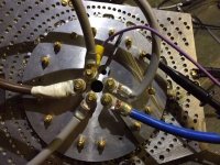
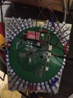
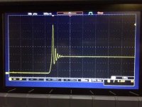
Had a quick look tonight with my scope closer to where it needs to be, I just put it where it would clip on, as I couldn't easily get it any closer. See images below of the controller.

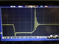
The results were far better, the scope image is taken at around 150A.

I think next I will try it at 48v, I just need to get hold of some battery's. How is the ringing likely going to be on double the voltage?

bottom.jpg
top.jpg
150a.jpg
 
I would't thrust any such measurement taken with the ground lead.

p.s. Doesn't your scope have a "save bitmap" function?
 
My scope does have a save bitmap option, but I don't know how to use it :oops: and I need to find a memory stick.

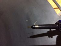
With the scope probe I have, the closest I could get it was using the attachment shown below. I put this across the S-D of the low side. Is this acceptable? I might have a lead at work with the ground ring closer to the probe tip which I can get directly across the FET.

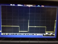
The biggest spike I could capture is below. With the trigger higher it didn't capture, I can't be 100% sure on the current, but I saw 230A on the clamp meter round the battery lead, so it would be in excess of this as the meter is slow to respond and the current reduces as the motor RPM increases. So I think this is about as bad as the ringing gets.

Should I be taking the controller apart and increasing the gate turn on resistors, or should I be moving onto a higher voltage?

probe.jpg
220A.jpg
 
trialspower2 said:
My scope does have a save bitmap option, but I don't know how to use it :oops: and I need to find a memory stick.

Njay: Usually there's a suggestive menu button, you set the output type and go save choosing a filename (or let it choose for you). Memory stick or your smartphone, if you use one.

With the scope probe I have, the closest I could get it was using the attachment shown below. I put this across the S-D of the low side. Is this acceptable?

Njay: From my point of view, yes. If you can get it closer then better, but what you have is the "minimum" you should do.

I might have a lead at work with the ground ring closer to the probe tip which I can get directly across the FET.

The biggest spike I could capture is below.

Njay: Huge!

With the trigger higher it didn't capture, I can't be 100% sure on the current, but I saw 230A on the clamp meter round the battery lead,

Njay: What matters is phase (motor) current, and it can be several times higher than battery current.
The hardest test you can do on the controller is to block the rotor and give it full throttle. You can make a "double pulse" test so you have constant, and therefore comparable, test conditions (https://endless-sphere.com/forums/viewtopic.php?f=30&t=63983).


so it would be in excess of this as the meter is slow to respond and the current reduces as the motor RPM increases. So I think this is about as bad as the ringing gets.

Should I be taking the controller apart and increasing the gate turn on resistors, or should I be moving onto a higher voltage?

View attachment 1
 
Since my last post, I have changed all the gate turn on resistors from 25R to 50R. I would say that if anything it has made it slighlty worse. I have also tried changing the synchronous rectification dead time, but it does not have any effect on the spike.

When running on 24V the spike upto 40v
When running on 36V it is upto 50v
When running on 48V it is upto 60v

Even when on 48V there is very little ripple on the DC bus rails.

Could it be the increase in gate resistor value has not helped because the spike is appearing during the switch on of the MOSFET before it is fully turned on?
 
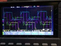
I have just been having another look over things and I noticed that there seems to be a large section where the high side is switched on. But looking at my pwm, this is not the case. Is this the motor generating the voltage??? The first image is at 500rpm or so and the next one full throttle. The channels are the 3 motor phases, with the purple channel on my make shift current clamp on one of the phase legs.

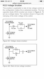
I was also wondering if the voltage clamp snubber in the other image might be helpful for me to reduce the turn on spikes?
View attachment 2
fullthrottle.JPG
snubber.jpg
 
trialspower2 said:
I have just been having another look over things and I noticed that there seems to be a large section where the high side is switched on. But looking at my pwm, this is not the case. Is this the motor generating the voltage?
Well, sort of - the inductance of the motor is.

What problem are you trying to solve here, exactly? You are seeing a spike because, during turn-off, the topside diode takes a few us to start conducting. You're never going to get rid of this completely. You can use faster diodes in parallel with the FETs but that might be solving a problem that doesn't really exist.
 
I the snubber suggestion was to try and reduce the spike as below
IMG_4419.JPG

I'm a little confused, is this biggest spike during switch on or switch off? I thought it was during switch on?
 
At switch off. As you try to cut the current on an inductance, it raises the voltage trying to counter act.
When the FET is ON, its Vds is very low.
 
Currently I have high side pwm (with synchronous rectification) with the low side switched on for the duration of the cycle. Am I not cutting the current when the high side switches off? and the synchronous rectification switches on to allow the current to flow without it going through the low side diode?
 
When you close a switch you're stopping current from flowing through an inductance (in the context of this thread, a parasitic inductance). If you sit down and draw your power bridge's schematics of the power paths, including the (parasitic) inductors on all connections, and do the exercise of simulating the current flow for both PWM input signal states, you'll see where you are cutting the currents.

trialspower2 said:
Currently I have high side pwm (with synchronous rectification) with the low side switched on for the duration of the cycle. Am I not cutting the current when the high side switches off?
I guess you mean with the bottom side switched OFF, or that would be a short. Synchronous rectification means top FET on & bottom FET off -> top FET off & bottom FET on and so on. When you close the top FET, current stops flowing through it and starts flowing through the bottom FET's body diode, for the duration of the dead time, then the bottom FET opens and current moves from the diode to the channel. This change in path cuts the current through the parasitic inductance between the exit point to the motor's phase and the top FET's source, causing it to spike the voltage (then the ringing comes from resonance with FET's parasitic capacitances).

trialspower2 said:
and the synchronous rectification switches on to allow the current to flow without it going through the low side diode?
The red part makes no sense, "synchronous rectification" is a technique's name and not some kind of switch.

You'll gain a big understanding of all this by doing the exercise I mention above. This stuff is much easier to see/explain with a drawing than by words. A thread to help: https://endless-sphere.com/forums/viewtopic.php?f=30&t=55641
 
Sorry, I think I have done a really bad job of explaining this...

Njay said:
I guess you mean with the bottom side switched OFF, or that would be a short. Synchronous rectification means top FET on & bottom FET off -> top FET off & bottom FET on and so on.

A) One phase of the motor is being driven with synchronous rectification. This is the high side, it is switching in a synchronous manor to control the speed of the motor. There is dead time between the high and low side switching.

B) One phase of the motor is switched low,

C) One phase of the motor is switched off.

Once the step is finish (when the next hall sensor is reached) the states swap to different phases.

What I am looking to do is to reduce the voltage spike so that I can run on 75V without it being to close to the maximum drain-source voltage for my fets. 150V. Currently it is reaching, but not exceeding 110V on 48V battery voltage.
 
trialspower2 said:
A) One phase of the motor is being driven with synchronous rectification. This is the high side, it is switching in a synchronous manor to control the speed of the motor. There is dead time between the high and low side switching.
Nope. The "high side" cannot be driven in "synchronous rectification", because synchronous rectification requires 2 switches, in your case, a high side and a low side. If you're driving your phase in synchronous rectification, then you are switching between "high side ON, low side OFF" and "high side OFF, low side ON". This is at the "PWM level"; the phase commutation that occurs to rotate the rotor is the next level in the "abstraction ladder", and isn't responsible for the FET switch voltage spikes you're seeing.

trialspower2 said:
What I am looking to do is to reduce the voltage spike so that I can run on 75V without it being to close to the maximum drain-source voltage for my fets. 150V. Currently it is reaching, but not exceeding 110V on 48V battery voltage.
The transient behavior of an inductor can be written as

dv = L di/dt

Therefore, to reduce the voltage spike, and assuming you want to keep the current, you need to either reduce L (layout parasitic inductances) or increase dt (switch the FETs slower; by "switch" I mean "the FET's transition from ON to OFF or vice-versa").
 
When I said the high side is being driven in synchronous rectication I should have said that this is in conjunction with same phase low side. It is definitely in synchronous, the pwm h/l is set to complementary mode in the pic firmware and it regens compared to free wheeling when not in synchronous.

I can't improve on the layout, the current loops are as short as possible. Adding resistance to the gates to slow down turn on did not help either.

Why do I not see the spike on the dc bus, it is there but only tiny. Would some schotty diodes between the phase and dc bus + not conduct some of the voltage back to the battery/ caps once the spikes exceeds battery voltage?

Cheers
 
The main caps should be absorbing the spike on the DC rail. Maybe you need more caps there, or closer to the FETs, or lower ESR caps.

It's ringing pretty badly on turn-on. Too much inductance between the main caps and the measurement point.
 
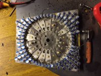
The caps are aluminium polymer, the layout is as below. This is the ring of high side transistors clamped onto the aluminium + bus plate, there is then a 0.8mm circuit board with a negative bus plate under it. The measurement point is at the other end of the bolts which go through the high side transistors. So its basically about 10mm of aluminium and 10mm of M3 brass bolt away from the transistor. I will try and take a measurement directly at the transistor lead to see if it makes any difference.

IMG_4332.JPG
 
You are switching really fast for that amount of current. Let's put things in perspective:

dv = L di/dt

di = 250A
dt = 40ns

A small piece of 10mm wire has like 10nH inductance just for some reference. Let's assume your layout has 5nH parasitic inductance from the FET to the phase output alone. That will result in the inductance generating, when you try to bring the current to zero (such as when turning off one switch to turn on the other), a voltage of

dv = 5nH * 250 / 40ns ~ 31V

which adds up to any DC voltages already present.
 
You need to reduce the switching speed on both sides. Will you need a 50 Ohm resistor? A 100 Ohm? A 500 Ohm? I don't know, you'll have to go up until switching speed comes down to cause acceptable voltage spikes/ringing. You can also add a capacitor in parallel with G-S. You can control switch on and switch off speeds independently with the resistor in parallel with a series diode-resistor technique. Search around in the forum, there are a few discussions around that.
 
What is the aim of the G-S capacitor? I presume it will slow down the turn on as it is charging? Is this not like using a fet with a really high reverse transfer capacitance? What about a G-S resistor, would slow turn on down and speed turn off up?
 
trialspower2 said:
What is the aim of the G-S capacitor? I presume it will slow down the turn on as it is charging? Is this not like using a fet with a really high reverse transfer capacitance?
No. Reverse transfer capacitance (also called Miller capacitance) is drain to source. The FET already has a pretty big G-S capacitance; it's inevitable when you are using a large FET.
What about a G-S resistor, would slow turn on down and speed turn off up?
Not really. They are useful when the gate drive can become disconnected (for example, during turn-on) but it doesn't change the speed much.

You've got some G-S capacitance there which forms one part of an RC filter. Calculate the R for the turn-on time you want then use that value for the gate resistor. If you want faster turnoff than turnon, then put a signal diode across the gate resistor.
 
Which parameter is the G-S capacitance on the datasheet? (FDH055N15A)

If the FET already has quite alot of G-S capacitance is there any different between adding more gate resistance compared to adding a G-S capacitor?
 
Back
Top