High side vs Low side PWM

trialspower2 said:
Which parameter is the G-S capacitance on the datasheet? (FDH055N15A)
Ciss, input capacitance.
If the FET already has quite alot of G-S capacitance is there any different between adding more gate resistance compared to adding a G-S capacitor?
Well, again, if you want a given rise time then increase resistance until you achieve the desired rise time. Rise time 10 to 90% is given by 2.2RC where R is gate resistor and C is gate capacitance. However, since you really only care about time to gate threshold (about 3V in your case) then that also depends somewhat on gate drive voltage. Increasing capacitance just increases loss.
 
So in an ideal world I would want to slow the transition up to 3V, but once 3v is reached get to 15V as fast as possible? As once 3V is reached the switch on of the FET has essentially completed?
 
trialspower2 said:
So in an ideal world I would want to slow the transition up to 3V, but once 3v is reached get to 15V as fast as possible?
Not really. Above about 5V the FET is, for all intents and purposes, fully on. (Data sheet goes into detail on this.)
As once 3V is reached the switch on of the FET has essentially completed?
Basically. Beyond that you get a very slight decrease in Rds_on. Again the data sheet shows how this happens.
 
I have realised that 75% of my turn on spike is gone when measuring at the high side transistor compared to the low side. It turns out that the different is over the M3 bolts which connect the high side to low side transistors. I used brass as its a better conductor than steel and all the aluminium bolts I could find were anodized. I have however found a source for 3mm copper bar, so I will get some of this and tread the ends to make studs. This will give more cross section area and be out of a superior material for conductivity. Hopefully this will drop the 48v spikes from 60v to under 20v which I will be happy with for now.
 
I have my doubts that changing to copper will reduce your spike... because it's the inductance that makes the spike, not the resistance.

Here's a diagram from another topic, just for reference as a half-bridge diagram with the parasitic inductors; the top FET (M2) is being used as a diode but it's functionally the same as it being independently driven. Motor phase is L1. When the top FET is ON, current goes through the parasitic inductors L5 and L7. When you turn it OFF in order to turn ON the bottom FET (M1), these inductors will create the voltage spikes as they are being starved of current. And similarly for the bottom FET, but with parasitic L4 and L6+L9.

file.php
 
I was thinking that something with lower resistance would have lower inductance? Also if I use a stud rather than something threaded it will work out slightly larger in diameter. However if you dont think it will make a difference, I will leave it as it is.

The project that we are undertaking is to build an electric trials bike, so there is plenty of work to do else where. The controller is at a point where we can try it on a bike, this is enough for the time being as we need to get a bike built, then refine everything later.

I have a new design for the controller with the high side transistor standing upwards and the low side sticking down. This will ensure that the souce and drain transistor pins are connected directly together while keeping DC bus extremely close and the circular shape for power sharing. It will also allow me to water cool the heat sinks easily. I will also drop down to 5 FET's rather than 6 as I think this is overkill for a 100v, 400a controller. thank you for your help, I will be back when the next controller is done!
 
I am bringing this thread back from the dead as I have now build my new speed controller and the bike.

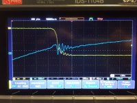
I am still getting a lot of ringing with my new controller when the high side switches on. In an effort to verify the controller design I have connected 3 large 18 ohm resistors across the outputs and run the controller at 70 volts. Under these conditions the switch on profiles are perfect with no ringing.

Do this prove the layout, or does it just prove that the extremely low resistance and inductance of the motor is required to cause the switch on ringing? If the ringing was coming from the controller, would it not still ring with a resistance only load?

thanks
Danny
 
trialspower2 said:
I am still getting a lot of ringing with my new controller when the high side switches on. In an effort to verify the controller design I have connected 3 large 18 ohm resistors across the outputs and run the controller at 70 volts. Under these conditions the switch on profiles are perfect with no ringing. Do this prove the layout, or does it just prove that the extremely low resistance and inductance of the motor is required to cause the switch on ringing?
You mean you added a load from output to ground? Then yes, a resistor will tend to reduce ringing, since that will make it a very low Q load.

However, that has nothing to do with the behavior of the circuit when you have a large inductance (i.e. a motor) attached. The behavior will be completely different once the motor is attached. Your initial ringing was likely due to a small capacitor/inductor network that you hit with a sharp rising edge from your inverter. The frequency of the ringing will give you some hints as to where the ringing came from. For example, if you have output capacitors, you can use that capacitance and the frequency to determine what inductance you are seeing. (likely a trace)
 
I put resistors across the three output phases to verify that all timings were correct. Next I will put a resistor from a phase to batt+ and a second from the phase to batt - with the intention of being able to analyse the dead time clearly. (Running Synchronous)

Will adding a sckotty diode across in FET help reduce the overshoot on switch on, or will it not respond fast enough? I get zero ripple on the DC bus.

I think the ringing period is about 20ns with the switch on taking 100ns
 
trialspower2 said:
Will adding a sckotty diode across in FET help reduce the overshoot on switch on, or will it not respond fast enough? I get zero ripple on the DC bus.
Well, if you want to do that, you don't need a Schottky. A hyperfast diode like an HS1D would be more appropriate. However, be warned that adding a diode adds capacitance, so the ringing might go away (or even get worse under some conditions) due to that, rather than to any clamping effect.
 
It's hard to get rid of all ringing. It's mostly a layout thing. Slowing the switching speed will reduce it, but increase switching losses.
 
trialspower2 said:
Forgot to say, the image is running a 25KW 50kv motor at a few hundred rpm
Ah, then you are seeing the entire system (including motor inductance.) It's hard to get rid of that completely. A snubber will help but will generally dissipate some power. Tuning the circuit with a capacitor may also help, but can do more harm than good if you don't know what you are doing. Slowing the turnon/turnoff with a gate resistor can also help (and is easy) but you lose efficiency.
 
Hello,

The layout cannot be improved I don't think. I have high side transistors sticking up, low side transistors sticking down with the d/s legs of high and low soldiered together with the copper phase connection coming off. They are only about 8mm apart. The bus + and - is only separated with the inner circuit board, with copper plate running to all the FET legs. I have over 100 x 22uf polymer caps with 2.2A ripple current each. The two models below are a similar design, I don't have the final ones to hand as I am at work. The bus connections are not on, they are a stud in the center with + on the top side and - on the bottom.

This is my third attempt and I believe I have optimised the layout as much as possible.

The gate drivers are plugged in around the outsides with the main control board plugged on the end.

I have increased the turn on resistors to 75R (originally 18R) to try and slow the switch. The gate drivers are high output and the FET's have a low gate charge which I think has lead to the very high gate resistor value. Switch off is on 8R resistors.

I am not sure how the spike will increase with current, as I have not yet pushed it. If it doesnt get much worse I am not to bothered. Its just if it starts getting alot bigger with more current.

I have not really allocated any space for snubbers as I wanted to avoid, I am considering removing a FET from each phase and replacing with a sckotty diode as I feel it might help route the spike back to the bus providing there is enough time for it to conduct. I could maybe place a snubber across the low side, I believe this is where it needs to be to help with the high side switch on, but this would be one for all the FET's not one per FET. I did wonder if there was some way of using a TVS diode to clamp the spike back to +, but I cant see how this would be possible.

I could try more gate resistance, as I feel the switch on is still quite fast? but then I am not sure what a normal switch on time is. I am current running at 100kHz, but I could reduce this, the idea was the high frequency would help with the spikes.

I will also tune the deadtime between high and low side complimentary switching, but I am not sure what amount of deadtime I should aim for, would 300ns be reasonable?


View attachment 1
 
Code:
Well, if you want to do that, you don't need a Schottky. A hyperfast diode like an HS1D would be more appropriate. However, be warned that adding a diode adds capacitance, so the ringing might go away (or even get worse under some conditions) due to that, rather than to any clamping effect.

Sorry, I mist this response before. Would a diode such as QH08TZ600 be a good choice? I can put them on high and low side in place of a FET and they have a 11ns reverse recovery with a decent current rating.

I was under the impression that schottky diodes had a faster reverse recover due to the different construction, however it is not a parameter which they list on the datasheet?
 
100kHz is higher than most controllers I've seen. 20kHz is more typical.
Slower PWM would allow you to slow the switching speed and keep the switching losses reasonable.
 
I could decrease the frequency, is this likely to make to turn on spikes worse? or will it probably not make any difference?

When the RDS on of a FET is so low, how can the ringing take place without it affecting the DC bus? Does it take place in the region where the FET still has some resistance as it has not finished switching? or is it the inductance across the FET so the resistance is not as directly linked?

When increasing the gate resistance, do you give with one hand and take some back with the other? i.e. the transition is slower which generates less energy for the spike, however it is easier for the spike to exist due to the resistance still present across the FET?

This one has been bugging me for a while, I suppose I should scope the gate voltage and compare to the ringing on the phase.....
 
Usually high PWM freq and high switching speed allows you to have less bulk capacitance however it's more demanding on minimizing layout inductance and capacitor ESR. For 100khz you would typically expect to see SMD mosfets and ceramic capacitors placed 1 or 2 millimeters from the drain. Through hole mosfet packages alone have significant inductance when switching large currents.

20khz PWM and slower switching speeds will be much less demanding but require 5x as much capacitance as the 100khz design. Typically you have to use electrolytic capacitors for these designs. Usually you only see 100khz motor drives in extreme situations where they're trying to make very compact controllers that only use ceramic capacitors to keep size and switching losses to a minimum.
 
Can you share the part number of the polymer caps that you are using?
 
trialspower2 said:
Sorry, I mist this response before. Would a diode such as QH08TZ600 be a good choice? I can put them on high and low side in place of a FET and they have a 11ns reverse recovery with a decent current rating.

I was under the impression that schottky diodes had a faster reverse recover due to the different construction, however it is not a parameter which they list on the datasheet?
Schottky diodes are fast, but you have very fast transients. Typically switching time is in the tens of nanoseconds. The SSA210, for example, is good for 100V 2A and has a reverse recovery time of 8 nanoseconds. Compare your actual transient to the switching time of your selected diode.

Also note that at those speeds you may not be seeing the real transients. Unless you have a probe socket on your board, it is likely that the probe leads are picking up nearby switching transients and adding that to the signal. (i.e. you can't use a ground lead or a long scope probe and get accurate results.)
I could decrease the frequency, is this likely to make to turn on spikes worse?
It will not affect the spikes.

When the RDS on of a FET is so low, how can the ringing take place without it affecting the DC bus?
AC impedance is very different than RDS_on (i.e. DC impedance.)

When increasing the gate resistance, do you give with one hand and take some back with the other? i.e. the transition is slower which generates less energy for the spike, however it is easier for the spike to exist due to the resistance still present across the FET?
The tradeoff is efficiency. A slower gate drive signal looks "cleaner" (i.e. less EMI) but you see more resistance losses in the FET.

Often you can ignore ringing like that. It's not going to cause the FET to avalanche at those energies, and it will likely change completely when you hook it up to a motor.
 
For bigmoose the capacitors are 22uf 100V polymer through hole off farnell, there is only a couple of options at this spec.


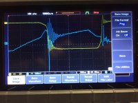
I have been experimenting with high gate values at turn on and turn off and it would appear that there is more going on than I originally thought. The below images are of the gate driver voltage, against the motor voltage on the phase. The motor voltage is in reverse as I have both scope grounds to the phase. (Only way to check both at once I think). It would appear that the ringing may be caused from the ringing on the transistor gate turning it on and off. You can see that the phase is following the gate oscillations. With the gate voltage dropping before recovering.

I am thinking this might be due to the low amount of capacitance in the FET's, and may be fixed by adding addition capacitance across the gate/ source to stabilise the voltage difference? And then go for a lower gate resistor value?

The other thing I was thinking about was making a two stage driver which ramps upto 10v slowly then switches on hard. I think this would reduce switching losses and make ringing more difficult??

IMG_7107.JPG
View attachment 2
View attachment 1
IMG_7110.JPG
 
You should scale down and then go up slowly. I think I've never seen a controller with PWM frequency above 32KHz for these power levels. If I read your last scopeshots correctly, the FET is not even having time to reach the final gate voltage before the cycle ends. Do you need 100KHz? What's the impedance of your motor phase? Decreasing efficiency by increasing switching time (which also decreases ringing and EMI) can be counteracted by decreasing switching frequency.

Another vital thing is how you are measuring. You have to use the ground clips (and not the leads) of your scope. Not always easy, but absolutely essential.

I don't think an external flywheel diode will help you, surely not an 8A one on a controller with a phase current of more than 250A.

So, I would say drop Fsw to 20KHz or a little less as already mentioned, adjust switching times to a few hundred ns, start maybe at 25V 25A. Then analyze and go up step by step in current/voltage. Use the same test all the time, the double pulse test is nice simple one. Reduce the variables.
 
trialspower2 said:
I am thinking this might be due to the low amount of capacitance in the FET's, and may be fixed by adding addition capacitance across the gate/ source to stabilise the voltage difference? And then go for a lower gate resistor value?
The ringing is likely not real; the FET isn't seeing it. You are seeing it due to poor probe connection. If you doubt this, keep your current connections and probe a ground plane somewhere else on the circuit, or a signal line known to be at ground potential. I bet you see a similar ringing.

1) The probe/scope should be isolated to reduce the amount of ground current you are returning.
2) Differential probes are ideal for applications like this.
3) If you are using regular probes DO NOT use the grounding leads that come with them. You must have the probe and its ground ring touching the device directly. They make sockets to accept the probe tip that helps with this.
4) When working with designs like this you need a current probe. They are expensive but are critical. Remember, a motor doesn't care about voltage; it cares about current, and switching current is the #1 job of the controller.

I assume that blue is gate and yellow is phase voltage. If so your gate drive is now way too slow.

One of the reasons I know that that ringing isn't real is that the gate voltage changes and the phase voltage changes are in phase. If they were real (i.e. if the gate were really going on and off that fast) the phase voltage would show the opposite response - phase voltage would get closer to zero as gate voltage increases.

The other thing I was thinking about was making a two stage driver which ramps upto 10v slowly then switches on hard. I think this would reduce switching losses and make ringing more difficult??
You are trying to solve the wrong problem. Get good measurements first.
 
billvon said:
One of the reasons I know that that ringing isn't real is that the gate voltage changes and the phase voltage changes are in phase. If they were real (i.e. if the gate were really going on and off that fast) the phase voltage would show the opposite response - phase voltage would get closer to zero as gate voltage increases.

Good observation. I've also found it hard to get good measurements with a scope on high powered stuff. Inductance of the ground lead becomes very significant at higher frequencies.
 
Back
Top