OK, so I'm about to mod my stock 40amp bluetooth controller to add a Cycle Analyst 6-pin plug to it, and since there's pretty much no room to fit the cable into the main bundle of cables leaving the controller, and simply because that bundle is a total mess... I figure it would be a good idea to eliminate some wires I'll never need (or at the very least, tuck them in the controller if there is room... so I'll at least have space to get the Cycle Analyst plug out with the rest of the wires).
So, I started off by listing the different groups of wires, there are 13 of them, in no particular order... describing the wires from the controller:
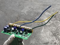
1) Main Power, 2 wires: red, black (thickest wires)
2) Phase Wires, 2 wires: yellow, green (thick)
3) Phase Wire, 1 wire: blue (thick)
4) Bluetooth, 4 wires: red, green, yellow, black
5) Throttle, 3 wires: red, green, black
6) Low Brake, 2 wires: black, grey
7) Low Brake, 2 wires: black, grey (same as above, but there are 2)
8) Manual Cruise, 2 wires: black, purple+white
9) 3 Speed, 3 wires: blue, black, pink
10) Power Switch, Hall Sensor... 6 + 1 wires: yellow, blue, green, red, yellow+green, black, light red (light red separate, goes to battery harness?)
11) PAS, 3 wires: red, green, black
12) PAS ON/OFF, 2 wires: black, black
13) Reverse, 2 wires: black, brown
OK, so it's obviously safe to say some of these will not be needed on this build... and some, I'm not 100% sure on, but should be easy enough to figure out...
#13 Reverse, I don't think there is any use of this on a mid drive motor, correct?
I assume the 2 Low Brakes (#6, #7) are for the 2 brake levers to add sensors to temporarily kill the engine when the brakes are pressed?
As for #11 and #12, PAS and PAS ON/OFF... I don't plan on using pedal assist at first, but it's possible I may consider adding it later (tho unlikely). BUT, if I were to add PAS later, and since I will have a Cycle Analyst v3... would the PAS be wired to the CA, instead of the controller, making these wires useless to me?
#9, 3 Speed Button, another connector I don't think I'll be using... again, I figure I'd be using the cycle analyst to limit the motor (if I ever want to, probably only for letting people test ride the bike)... I don't think I need to keep this around either
#8 Manual Cruise, presumably this lets you add a cruise control switch... something I don't plan on doing right now, tho may come up in the future... tho, I am not sure about this, but is this also anoth control that could be wired to the CA instead of this connector?
#5, Throttle.... normally I would think this is a must have/important... BUT, again, since I am going to be using a CA v3, I'm pretty sure I would wire my throttle into that, so this is likely also unnecessary, right? (given, I may not entirely remove this, just tuck it away)
I think that pretty much covers it... aside from the connectors/wires that are completely obvious that I need. Can anyone confirm my thoughts on these?... I figure the ones I will never need, what I could do is simply cut the wire inside the controller, removing the connector and excess wire, but leave a stub that I can place a label on in case for one reason or another I decide to reattach the connector (or a new on for that matter). Of course I would wrap the stub in electrical tape, or similar, to make sure it never gets shorted out or anything like that.
On a side note, I dug up this post from a google image that caught my eye: https://endless-sphere.com/forums/viewtopic.php?f=31&t=81711
That upgraded mount looks amazing compared to the stock setup. Does anyone know if there is anywhere to get this, or something similar to it now?... I definitely want one!
Also, whats up with this washer mod I hear mentioned a ton of times, but can't seem to find a single post with working photos/diagrams... let alone just some photos floating around. Can anyone point me in the right direction?