Ecolocycle controller info? Or best guesses?

drawk

10 mW
Joined
Oct 24, 2017
Messages
33
Location
North Bay, Ontario
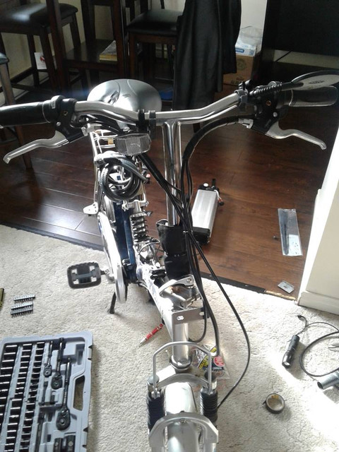
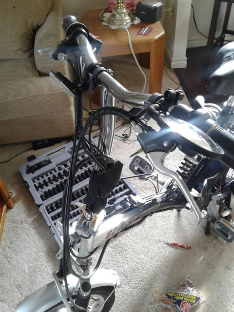
The background: I recently had my Emmo bicycle style ebike stolen. Thankfully, the battery was upstairs charging. Being with a 36v 11aH silverfish style battery and no bike, I was looking into converting a mountain bike, but came into contact with a gentleman who had a bike but no battery, and $50 later, came home with the bike pictured in the attachments. I can't quite identify the model, I imagine it is discontinued as I don't see it on any of the Ecolocycle dealers inventory. With a bit of modification to the leads, got it up and running - it has pedal assist in addition to the throttle and I am getting between 20km-25km/hr.

I was hoping that someone might have some information on the Ecolocycle controllers. I've searched, but I can find none. What I am trying to determine is if I can run this up to 48v. A couple of things: the Ecolocycle pages use language such as "25km/hr as limited by controller." and sure enough, that seems to be exactly what I hit at the top-end. Does anyone know if there is, in fact, a controller based speed limit on these?

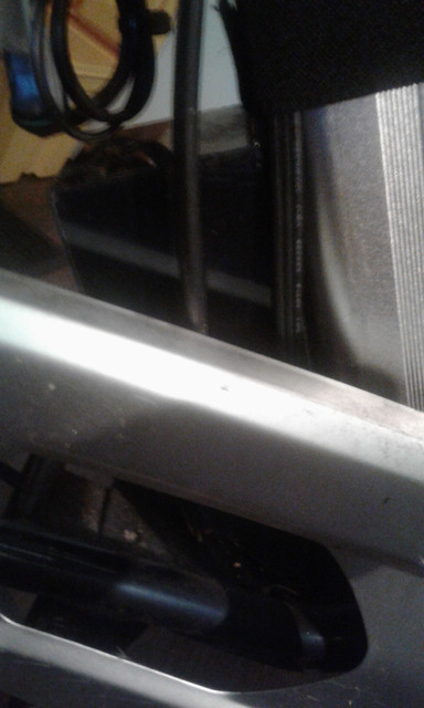
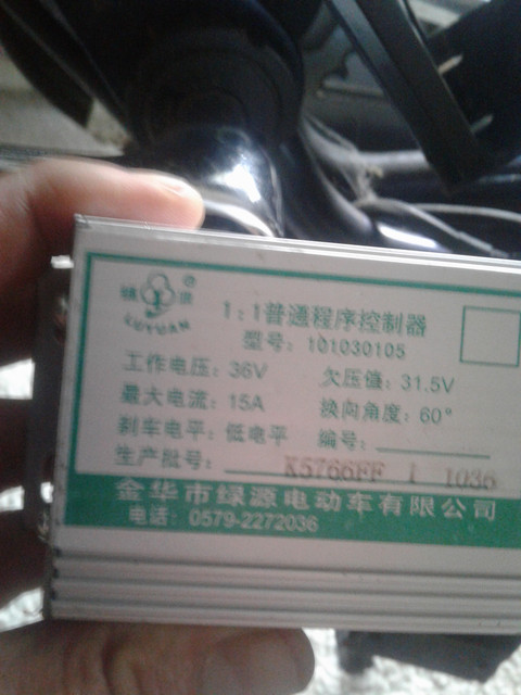
The controller is in a sealed black box. Hard to see, but took a pic of the exterior (not that there is much to see) on the frame behind where I have strapped the battery. I haven't looked too much to see if there is a way in, but it doesn't look like a simple task. If I do need to find a way to open it, I can presumably check the capacitors to get an idea, yes? Although, again, if anyone knows anything about these offhand, I'd appreciate any info.

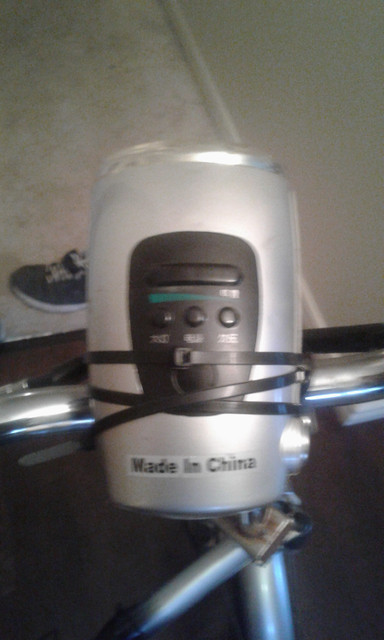
Apologies for the blurriness of the pics.


There probably is a speed limiter in the controller. You can see if there are any connectors that have only a single wire in them, that loop out from teh controller and then right back in without going anywhere. Sometiems those are used to enable/disable a speed limit.

Sometimes i'ts in the settings in teh controller MCU, and sometimes those can be changed from the display (if any) and sometimes they can't.

As for the higher-than-rated voltage, two things:

The controller's LVC won't protect the battery, and/or any power meter it has won't read correctly. It may also have an HVC that prevents it from being used at a higher voltage.

The internal parts of the controller need to be rated for the higher voltage (up to 58-60v for a "48v" battery, depending on chemistry and number of series cells). You'd have to open the controller up and then note down the numbers on the FETs, then look them up on the internet to see what their voltage rating is. You'd want something that can handle 75v for safety margin. Then you can look at the metal cans (capacitors) and see what markings they have for voltage. All the big ones need to be rated at least as high as the battery voltage, preferably significantly higher for safety margin.

Most of the other stuff would probably be ok, but no guarantees.

Looks like there are also other posts about the company on ES, if you look thru these posts
https://endless-sphere.com/forums/search.php?st=0&sk=t&sd=d&sr=posts&keywords=ecolo*+-ecolog*+-ecolot*+-ecolocap*
there is some info about them, possibly valid contact info, etc., that you could use.
 
Thanks for the reply. I pulled the controller out this afternoon and it is a Luyuan 36v controller (image attached). I've googled and searched here, and while there are several mentions of it (seems to be a common cheap controller) I can't, as of yet, find any wiring info.

I wish I had thought to take a picture of it, but I did locate a blue wire with a connector that seems to loop back in (the appearance is of two blue wires with a black connector at the end, unattached to anything) I can't tell whether it is just for connecting something that isn't needed or if it is in fact the speed limiter. Given that there is nothing attached, I will disconnect them and see how that goes.

Haven't had a chance yet to peek inside the controller box itself, it will be a project for tomorrow to get pics of the caps and FETs. I *have* found an image or two of the inside of the 48v version.

 
Well, here is the wire in question. I ended up cutting the connector end off the end, but am still maxing at just under 15mph (23kmh)

Ultimately I am thinking of replacing the controller with a 36v/48v but by the time it arrives from China, it will be well into the winter weather. In the meantime, still messing with this. Tomorrow afternoon's project will be to get rid of the monstrosity of the light/ignition/battery gauge piece. A whole lot of wires to disconnect in there and re-wiring necessary, I am sure. Hoping that it operates without it.


Wait a sec.. looking at the pic, I don't remember that red wire looking so clearly like a loop. Perhaps I had my attention in the wrong place?
 
If that's an image of someone else's unit, it could be different than yours. It's not that uncommon for different batches of controllers/etc to look totally different, or even to have different kinds of wiring.
 
The pics are all of mine. When I get it opened up again, I will check out that red wire - not sure if it is just a trick of the camera angle, because it certainly didn't jump out at that like me until I posted the pic.
 
So that red loop - on the controller, there is one black wire, one red wire, and a thinner red wire running to the plug. On the connecting plug, the black and red wire run to the battery connection and the thinner red wire - as pictured in the previous post - is just a loop. Unfortunately, snipping the loop and leaving the two other wires intact results in power and everything seems fine until I twist the throttle. Nothing. The motor/wheel does not spin. I've since reconnected it. It certainly does look like the culprit as far as governor goes though, I think ... so I am wondering if there is an extra safeguard so that it need to be connected.

I am wondering if it might be in the 'display' device (such as it is) which is a headlight, a battery gauge and a power indicator. (pictured below, front and back.) I want to get rid of that thing anyways as the headlight is damaged, it doesn't attach the bike well, and it is just plain ugly. I'm not sure what I am in for though, it might get in over my head.

Do you think it is possible that there could be a check in that thing?


drawk said:
So that red loop - on the controller, there is one black wire, one red wire, and a thinner red wire running to the plug. On the connecting plug, the black and red wire run to the battery connection and the thinner red wire - as pictured in the previous post - is just a loop. Unfortunately, snipping the loop and leaving the two other wires intact results in power and everything seems fine until I twist the throttle. Nothing. The motor/wheel does not spin.
Then that is what's commonly called an Ignition or Keyswitch wire. All it does is run battery power back into the controller to power up the low-voltage regulators, and turn on the MCU/etc.


I am wondering if it might be in the 'display' device (such as it is) which is a headlight, a battery gauge and a power indicator.
What wires go to it? Is it just power? If so, then there's no limiter up there.

In every case I know of where the limiter is "external" to the controller, the limiter is either just a loop of wire that comes out of the controller and goes right back in.

In every other case it's internal to the controller, where it either is a jumper on the board, or an internal wire loop, or programming in the controller (which isn't alterable unless you have the software to do it, specific to that controller).

It *could* be something other than that, but probably not.


In some cases you can also disconnect an external speed sensor, which of course means it can't detect the speed, so it can't limit it. But some will not operate without the sensor or they time out after a minute or few. Also, some use the motor halls as the sensor, so you can't disconnect or mess with it, cuz the motor won't work.
 
Thanks, this is great info. If I accomplish nothing else with this, I am learning lots which is good because a winter project is going to be starting a new bike build (thinking front wheel hub on my mountain bike)

As for this one, I will may order a 36v/48v controller eventually, unless I manage to find a way to get this up to at least 20mph instead of 15mph. I keep waffling between 500w and 750w and 1000w. Leaning towards 750w to be on the safe side vis-a-vis what the motor can handle and also for consideration of range - although I typically do short rides back and forth doing errands, with plenty of time to recharge between journeys if needed, and even with my Emmo that got stolen I have never come anywhere close to running out of juice on the 36v 11aH battery.

The external unit has pretty much everything connected to it except the battery connection, what I believe to be the PAS, and possibly one or two more wires to the motor. It is pictured (front and back) in my previous post (2nd and 3rd images.) I'm guessing it is a circuit board in there, so I really do hope that, speed limiter or not, it at least functions without it because I'll probably have to either desolder everything or clip and reconnect the leads. But I'm getting ahead of myself, I will open it up when I get home later today.

At that time, I'll probably start a new thread about that. I'm fairly new to ES, and thinking that I'd get better traction posting that experiment to "E-Bike Technical" forum vs. the "Electric Vehicle Technology" forum. You are being an amazing help, it is really appreciated. BTW, I saw your "Raine Trike Build" thread, and that is *awesome*!
 
drawk said:
As for this one, I will may order a 36v/48v controller eventually, unless I manage to find a way to get this up to at least 20mph instead of 15mph. I keep waffling between 500w and 750w and 1000w. Leaning towards 750w to be on the safe side vis-a-vis what the motor can handle and also for consideration of range - although I typically do short rides back and forth doing errands, with plenty of time to recharge between journeys if needed, and even with my Emmo that got stolen I have never come anywhere close to running out of juice on the 36v 11aH battery.

If you get a controller like the KT (kunteng) or LS (li shui) types, you can get them with an LCD that allows you to change their settings like power levels, etc. (and Stancecoke and Casainho are writing new firmware for those to give even better control). Just make sure you get the LCD *with* the controller or it may not be compatible--not all LCDs work with all controllers.

Then you can use it with the small motor on this thing (which probably isn't able to handle high power for very long), and then use it later on a bigger motor.

I've found that generally unless you have lots of hills or wind or constant stops and starts with a heavy bike (like mine), power level doesn't affect the range that much, assuming you are at the same speeds regardless of the power you have.

But if you *need* faster acceleration from a stop (like in traffic), or to climb a hill, or ride against hefty headwinds, *having* that higher power is very useful, even though it does use the battery up faster (and is harder on the battery and motor if they're smaller).


The external unit has pretty much everything connected to it except the battery connection, what I believe to be the PAS, and possibly one or two more wires to the motor.
If it has more than just battery power to it, you'll have to trace the wires inside and outside, and draw up a diagram of what goes to where. Then you can use that to help figure out if you can bypass the unit or not. You'll probably have to open the controller up to note what wires go to which pads inside that, too. (sometiems the markings make it easier to tell what's what, sometimes they don't).


If it's like one of the Fusin headlight units I have, it does have wires that go into it from throttle/brake on the bars, and then it just passes those back in a bigger cable (which also includes battery for the lights, power meter, and keyswitch) to the controller. But it isn't required--one can wire the keyswitch as just a loop (like yours has), and the brakes aren't required unless it does regen braking and you need that (or you want a cutoff for emergencies/etc). Then the throttle just has to be wired back to the controller separately.

The Fusin looks a bit like the one you have; mine was actually made by Wu Xing, but included in a motor kit by Fusin (no longer around).

At that time, I'll probably start a new thread about that. I'm fairly new to ES, and thinking that I'd get better traction posting that experiment to "E-Bike Technical" forum vs. the "Electric Vehicle Technology" forum.
I'd recommend asking a moderator (green or red names) to just move this thread there, instead of starting a new one, so you have all the info in one place. ;)


You are being an amazing help, it is really appreciated.
I like helping where I can, and when I have time. Pays back what others have helped me in various ways, too.


BTW, I saw your "Raine Trike Build" thread, and that is *awesome*!
Thanks--have you seen the SB Cruiser--it's the older big brother of the Raine Trike, built to haul my St Bernards, their food, and other cargo:
https://endless-sphere.com/forums/viewtopic.php?f=2&t=67833&start=600#p1324091
Like most of my stuff it's evolved as I've learned and used it for things, so it's a fair bit different now than it was when it started out. :)

THe Raine trike is built from what I've learned there, and I'll use things I learn from the Raine Trike to update SBC, or build a new version someday.
 
That is a wild looking trike! :eek:

So, I managed to get rid of the headlight/ignition/horn/led piece without any problems. I disconnected and reconnected everything one piece at a time to avoid confusion, and took the opportunity to label the function of each connection with painters tape (where I could determine it.) I wrapped everything up in a plastic bag held around the cord bunch with an elastic and slipped that into a black fabric zip bag held to the handlebar with a plastic tie.


While working on this, and having the containing controller box open, I made a discovery. That blue wire from one of my earlier posts that I had snipped the end off is in fact the governor/speed limiter. I am starting to understand things a bit better ... the connector on the end had no loop on it, so it was already disconnected. So I'd done nothing by clipping it. I discovered this because I figured I may as well 'fix' that wire by stripping both ends and twisting them together, and low and behold the speed dropped by about 60%. This was 50%-60% (I estimate) of the 15mph where it normally maxes out, so I do think the 15mph is programmed into the controller.

I can take the ends of the controller itself just to peek to see if there is anything suspicious on the board itself, but I can't for the life of me get off the screws on the sidepanel that connect into the rail holding the circuit board, so for now I've given up opening up the controller. Unless I can just tap the board out (I have seen some posts that lead me to believe that may be possible) - I am not sure. I can see enough though through the ends to see that the capacitors are rated at 50v.

Regardless, I am planning on ordering this tomorrow, which has a KT controller and a reasonable shipping time within budget range:
https://www.aliexpress.com/item/36V...l-Panel-Twist-Throttle-Brake/32649030728.html unless you would advise otherwise.
 
drawk said:
So, I managed to get rid of the headlight/ignition/horn/led piece without any problems. I disconnected and reconnected everything one piece at a time to avoid confusion, and took the opportunity to label the function of each connection with painters tape (where I could determine it.)
If you'd like to contribute to future seekers of knowledge, you could post up the info in this thread. ;)

This was 50%-60% (I estimate) of the 15mph where it normally maxes out, so I do thinkthe 15mph is programmed into the controller.
Well, at least you (probably) know now. :/

but I can't for the life of me get off the screws on the sidepanel that connect into the rail holding the circuit board, so for now I've given up opening up the controller. Unless I can just tap the board out (I have seen some posts that lead me to believe that may be possible)
That rail is what the FETs are bolted to, so you can't tap the board out without breaking the FETs off the board, until you first unscrew the rail from the case.

Sometimes they use loctite to secure those screws, sometimes they're just crappy metal and strip out the heads easy. In that case you'd have to use a screw-remover for that type of problem, or cut slots in teh screws and use a flatblade screwdriver. Or grind the heads off, pry teh bar away from teh case far enough to let the screw bodies pull completely thru the holes in the case so you can tehn pull the board out of the case. Doing that means you then have to get the screw bodies out of the bar with pliers or similar, and then replace them with new screws. Probably not worth all that just to peek inside, at least not until you have a new controller available in case this one is broken in the process. ;)


regardless, I am planning on ordering this tomorrow, which has a KT controller and a reasonable shipping time within budget range:
https://www.aliexpress.com/item/36V...l-Panel-Twist-Throttle-Brake/32649030728.html unless you would advise otherwise.
Looks like a typical kit; basically like my old Fusin (LiShui) one, which worked fine, except a bigger actual controller. Note that they say 500-750w, but the current limit is 25A, so with a 48v pack it'll be about 1200w. 36v pack gives 900w. You wouldn't see that usage constantly except on hills or against stiff headwinds, though.
 
If you'd like to contribute to future seekers of knowledge, you could post up the info in this thread.

Plan to do so :) I took some pictures and just need to edit them a bit to visually label them. The existing information on this thing is scarce to non-existant.

In that case you'd have to use a screw-remover for that type of problem, or cut slots in teh screws and use a flatblade screwdriver. Or grind the heads off, pry teh bar away from teh case far enough to let the screw bodies pull completely thru the holes in the case so you can tehn pull the board out of the case. Doing that means you then have to get the screw bodies out of the bar with pliers or similar, and then replace them with new screws. Probably not worth all that just to peek inside, at least not until you have a new controller available in case this one is broken in the process.

A project for another day, perhaps, lol. I don't really have the tools for any of that on hand. I ordered the new controller this morning. The legal limit here in Ontario on the roads is 32kmh (~ 20mph) - I'm looking forward to getting at least that. It wouldn't be so bad if I could compensate with pedaling, but when it tops out, pedaling just results in the pedals spinning as though the rear wheel was off the ground. Even on the bike paths, the regular bicycles blow past me. My previous bike cruised along at a good clip, at least > 40kmh on flat or downhill. I hope whoever jacked it is treating it well. :roll:

All in all though, this one is becoming a labor of love, and now I've got a new hobby. I will likely use this controller, the throttle and brakes, the PAS disc, and the speed sensor on the mountain bike conversion ... so I should just need the motor to start that one off and can swap the battery between them as needed.
 
Hope you are still out there amberwolf, as I'm in a bind :)

Got my new controller. I've set it up along with the LCD display, but am running into a problem with error code #3 (Motor Hall Sensors) -- the problem is that sometimes the motor starts spinning, but then stops with quickly with this error. At other times, it doesn't spin at all, just immediately goes to the error.

Now, when it does spin, I know that that the phase/hall wires are a little off as it seems to want to spin backwards. I've done enough searching and reading to know what needs to be done there in terms of switching 2 hall wires and 2 phase wires and then experimenting with different combinations of the phase wires until I get smooth forward motion. Unfortunately, I am not even there yet, as I can only rarely get the motor to engage at all before erroring out. And again, it normally just errors out without engaging at all, even with the same hall/phase wire configuration(s) that sometimes getting it going for about a second.

Concerned that one of the hall sensors might actually have gotten damaged, and to rule out the possibility of just the wire having gotten damaged or come lose, I disconnected the new controller and reconnected the old one and it worked fine. Disconnected the old controller again and reconnected the new one again, and the same problem persists.

Sooo close :( I don't know if it is an actual sensor problem (if so, why would the old controller work?) or an issue with the programming through the LCD. Some of the values I just had to leave at the default, because I didn't know exactly what to put in. Or the controller.

[edit: topic has been moved to e-bike technical now ... thanks Ypedal]
 
Doing a bit more experimenting ... when I power up and slowly rotate the pedals by hand, the speedometer on the LCD shows the speed, so that is registering, but when I add any throttle (well, not actually throttle, see next paragraph) the back wheel locks up and then the LCD shows the error code 3 message.

I took the throttle out of the loop for troubleshooting purposes, thinking at first that it may be the culprit, and for ease of testing. To add power, I am presently holding down on the "Down" button to kick in the 6km "walk mode"
 
The most likely problem is wrong phase/hall combo. If you have a current meter (or multimeter with 10A setting), I'd use that in series with your battery wire to controller, to monitor current while testing different combinations.

First test it with your old controller, to show you what the no-load current *should* be.

Then start trying different combinations with the new one, until you get a forward combination with similar no-load current.

Also only test with the throttle just a teensy bit until you're confident of a good combo (you can damage the controller with high throttle bursts on a wrong combo).


Also, many controllers have self-learn for the phase/hall wires, so you just hook it up in whatever order, then use the self-learn wires and it automagically detects the right order and uses them that way wihtout you changing any wiring. That's usually a wire loop with a single-connector (similar to what you were previously looking for as a speedlimiter on the old controller).
 
I wonder if self-learning might actually account for some of my frustration. For example: Let's say I have a setting, and it has one result (say, choppy forward movement) - ok, progress. I power off and disconnect. I reconnect to make sure it is consistent. It is. Good. I make note of the wire configuration and the result. I move on. I hit a combo that just gives me error 3. I power off, disconnect, try it again. Still error 3. Ok, I make a note. I try the first combo again just to see. Now I get a different result (maybe a 'different type' of movement or speed, maybe error 3, etc..) Then error 3 again for everything. I try reseating wires, and eventually give up because everything is now just 'error 3' including the initial configuration that was working (with choppy movement but no error code on the LCD, which, again, is progress)

I come back an hour or so later 'just to see' and then the motor does something again, although often different than what it did in that configuration before.

It has got to be either that, or a problematic wire. If I could get repeatable, consistent behaviour, I am sure that this would be done by now. As it stands, most of the time, I am stuck on just "error 3" with no motor action.

The next time I get it to even move at all, I am *not* going to power off between phase wire switches, and only power off after I have the one that I want it to remember.

Right now, I have I spent all day tampering with this thing and am getting grumpy :lol:
 
Every wierd problem I've had with stuff like that is a connection problem, usally but not always in the hall sensors or the power or ground to the sensors. Mostly in the connectors themselves, but sometimes in the wires themselves, or the crimps. sometimes a pin that is backing out of the onnector as you push them together-=just enough to have an intermittent onnetxon.

Since the mtoor works with the old ocntroller, the most likley place for the problems is in the new controlelr's wires or connectors.
 
Before going further, check that the hall sensors are working. Connect everything and power it up. Stick your voltmeter probes up the back of the hall connector red and black wires. You should have around 5v. Then test between black and each other wire while you turn the wheel slowly backwards. You should see 5v switching on and off.
 
Since the old controller is still working, I expect the halls do work in the motor.

But there is a hall-related issue that could appear to be a hall problem (but isn't): one or more of the pullup resistors inside the controller might not be connected. That would cause a hall to not have 5v on its' output at all, and appear to toggle only very slightly (or not at all) above 0v.

The test d8veh suggests would reveal this, too, if the test is done both on the original controller and on the new one, if the results are different.
 
Thank you very much, both. This is helpful.

I had to go purchase a new multimeter as mine either has not bmade the move yet, or is packed up who knows where. I cut off a bit of extra protective rubber from the ends of the leads so that I could get them into the back of the hall connector. I am getting alternating between 0 and 5v between black and each colored hall wire. I also checked continuity from inside of the backs of both sides of the connectors and that checks out.

One of the things that I've discovered while testing out hall/phase wire configurations it that I usually have to turn the peddles with my hand to order to get the motor to engage. This may be setting related, although I am fairly certain I had it set to not require peddle action before engaging the motor. And while I have what appears to be smooth forward motion, when holding down on the down button (to trigger 'walk mode') when I use the throttle it cuts out. This may be an issue with the new throttle - my old one has a different wiring configuration, but I should be able to jimmy it up to try it. Either way, I still get error 3 on the display, although the motor will continue running (in 'walk')

So, given that I am still uncertain that I have the correct phase/hall, I guess my next step is to do as amberwolf suggested about running the multimeter in series with the old controller and then the new one?

One of these days I'll get up and running. Snow coming next week, so hopefully before then :)
Thanks again.
 
Ok, so I found that one of the reasons that I was having difficulty getting consistent results was one of the hall wires was disconnecting intermittently, due mostly to a lack of length on the wire on the motor side and some resulting downward tugging by the weight of the controller. Another was that I needed to crank the pedals a bit with my hand to get it to engage, which ended up being the C4 setting (needed to be set to 3.)

I measured the no load current of the old controller and it is 0.3. I am currently going back through the hall/phase combos. Some that I thought were "stuck" were probably due to the wire and/or needing peddle action. While I still get the error code for most of the combos, there have been one or two that, while not the right setup, did not trigger the error. So I am optimistic.

Thanks again.
 
I came across a post here on ES (don't have the link handy at the moment) that suggested that some of the error 3 problems the individual had was related to a misaligned PAS sensor. I had not installed the PAS sensor that came with this kit, so I will install that just to rule it out.
 
That bad connection is the most common reason for problems.


Side note:

If the PAS wasn't installed, then the controlller couldn't have detected pedal movement. That means that whatever happened when you moved the cranks to cause the motor to spin or error to go away caused something entirely different to occur--possibly another loose wire, etc. being bumped by the cranks or chain or whatever.

If moving the crnaks didn't make the rear wheel move, without a PAS sensor installed, it shouldn't have affected the system at all.

If moving the cranks made the rear wheel move, and the motor is in the rear wheel, then that would change the position of the magnets relative to the hall sensors and so could make a motor start moving a bit and allowing the controller to spin it even under certain wrong combos or a right one with a missing hall sensor signal.
 
Ah, yes, makes sense. I'm about to pack it in for awhile with the new controller, I think, and run the old one for a few days just to get back on the road, as I am just not sure what to do next. I guess it would be taking a look inside the motor at the sensors? Not sure why it runs ok with the old controller.

I'd be happy enough to just not worry about the error code on the display, or just not use the display entirely, except with even what I believe to be the correct combo (I have been going back through trying each of the 36 combinations again, now that I am certain that everything is connected as well as I can get it) I have throttle issues - and it is the same with both the new and the 'old' throttle. It will throttle, but then cuts out after a second or two, even if I hold it low and steady. However, releasing it and then twisting it again, it goes again, then cuts back out, etc.. Interestingly, if I hold the "walk" function instead of using the throttle, the motor continues running along just fine without cutting. So not sure if it is the cable running into the controller from the throttle connector or related to the (probable) hall sensor issue or what. I've tried dozens of different P and C setting combos, reset factory defaults, etc..

I can't test with PAS as I am waiting on a crank puller to be delivered so that I can install the disc. *sigh* Haha. I guess when I do take this controller off, I will do what I can to open it up and poke around inside.
 
Back
Top