KT motor controllers -- Flexible OpenSource firmware for BMSBattery S/Kunteng KT motor controllers (0.25kW up to 5kW)

timmy66 said:
Are you concerned that you won't have a platform for using it if BMSBattery stops selling this? Or if you've gotten the schematic well documented, maybe invite someone else to produce the hardware so there's no issue with availability?
Not concerned at all because they have a long history by now, more than 7 years and still selling the same cheap controllers like the famous KU63. I am doing just the same others did, buying, learning their controllers and hacking them. But now this new ones (with STM8S) are programmable and so the hacks will go deeper :)

And yes, for making hardware, we just need a LOT of money :)

timmy66 said:
Frustrating shipping costs from BMSB are about the same as the controller price :(
Would you have a better alternative in USA? I bet not.
 
casainho said:
The firmware on it's current state, is a serial killer of Kuntengs :)
...
- On the last 3 days did repair my S12S 3 times, exchanging burned mosfets. In the end, I started to use S06S with 48V and I also burned all my S06S!!

Puhhh, that are really bad news. :shock: :( . What kind of fuse do you use in your setup?

I corrected a little thing in the code of the "Torque-Simulation" branch today.
Code:
uint16_t ui16_BatteryCurrent_accumulated = (-1*current_cal_b)<<3;
Whitout this it takes quite a long time, until the filtered current value reaches the correct level and meantime the current control loop sends the real current to Nirvana. But this only happens at the very first seconds after powering up the system.... For a faster response, we should lower the number of samples for filtering, perhaps.

I think, I'll try the Torque-Simulation Branch with my bike in the next days, to see if something goes wrong. With my test bench, I had no problems for many test sessions now, except the thing with the filtered current value. The firmware never freezed while drawing high currents, so far.

regards
stancecoke
 
stancecoke said:
Puhhh, that are really bad news. :shock: :( . What kind of fuse do you use in your setup?
No fuse, I went straight from the lab power supply to the battery pack with BMS. Do you use a fuse? which type and value do you recommend?

stancecoke said:
I think, I'll try the Torque-Simulation Branch with my bike in the next days, to see if something goes wrong. With my test bench, I had no problems for many test sessions now, except the thing with the filtered current value. The firmware never freezed while drawing high currents, so far.
Be careful about that thing of current at startup/motor blocked.
 
Oh yeah, just moved the phase B current sensor from my burned S12S to a S12P I bought from my friend workshop of EBikes -- flashed our firmware and it runs perfectly my Q85 motor <-- this is flexibility, an advantage of our OpenSource firmware :)
Since I remember, Stancecoke did the same operation S06P --> S06S.

I was expecting this controller to work at 24V but it only works at 48V, not at 24V nor at 36V.

 
casainho said:
which type and value do you recommend?

I will use a wire integrated fuse-holder with a 10A fast acting fuse, and limit the current to e.g. 8A in the code first. If this works stable, I can use higher values for the fuse.

casainho said:
Be careful about that thing of current at startup/motor blocked.
I will test with a direct drive, in this case the motor can't block in a PAS-mode. The motor can only start, when the pedal is turning, if the pedals are turning, the motor has to turn, too :wink:

regards
stancecoke
 
I implemented the moving information on display and it is useful even when developing/debugging:

Code:
  // prepare moving indication info
  // the first ifs have higher priority!
  if (brake_is_set ()) { ui8_moving_indication = (1 << 5); }
  else if (cruise_control_is_set ()) { ui8_moving_indication = (1 << 3); }
  else if (throttle_is_set ()) { ui8_moving_indication = (1 << 1); }
//  else if (pas_is_set ()) { ui8_moving_indication = (1 << 4); }

I was able to mod my S12P 48V to be a S12S 24V. For the voltage it is the easier part :) -- just change the power resistor the drops the voltage and I had some from S06S controllers that are now burned.

I documented the mods here: https://opensourceebikefirmware.bitbucket.io/Motor_controllers--BMSBattery_S_series--Hardware_mods.html

56-6.png
 
I am thinking how to implement max current protection and the nominal current protection.
I remember to see some S06S that said continuous current 7A and max current 15A.

When to use the max and the continuous current? I think max current only for startup, where the max power should be needed. The startup may start at velocity 0 up to a x velocity and for a limited number of seconds like 3. After the startup, the current should switch to continuous current value - and maybe the switch be done as a linear down ramp.

And so my idea is:
- startup starts when erpm = 0 and with current limited to 15A
- startup ends when erpm == sinewave erpm value or start time > 3 seconds and current decreases in a linear ramp to 7A, during the next 3 seconds

What do you think?
 
Hm, it should be quite easy to check the behavior of the original firmware. I don't believe, that it reduces the power that fast....
I think, checking that the motor turns with a certain speed when it draws high current is much more important.

I don't know exactly what killed our Mosfets, but a load of 15A should be possible over several minutes and you should recognize the housing of the controller is getting very hot, before the Mosfet burns, have a look at the Datasheet of the used Mosfets....


regards
stancecoke
 
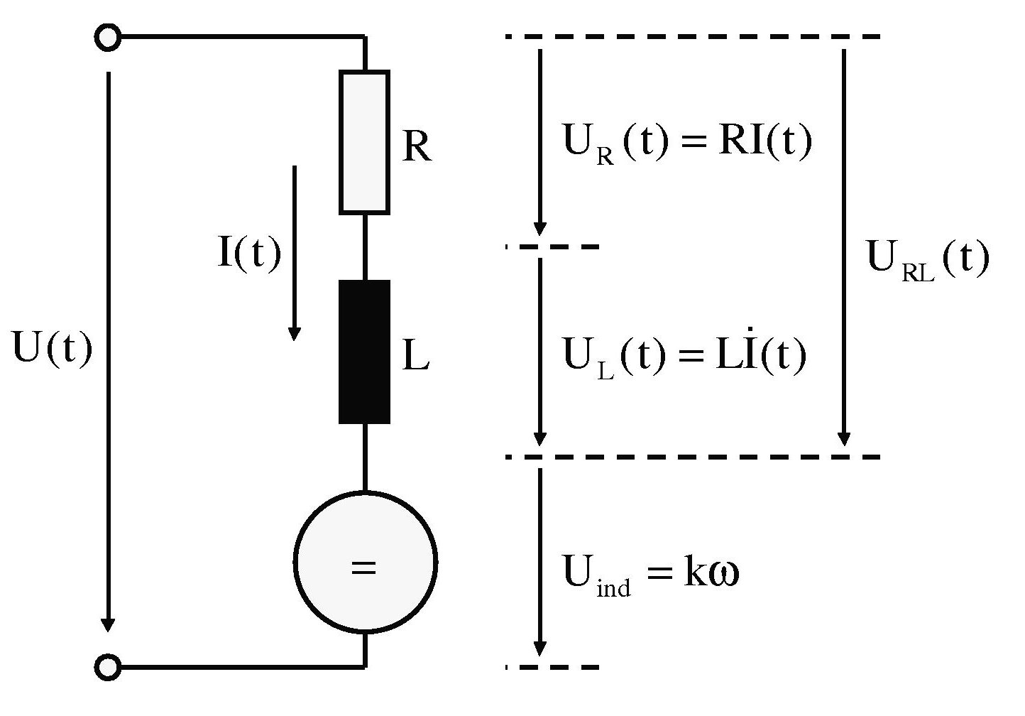
motor current = (effective voltage - back EMF) / resistance

back EMF = RPM * Kv

effective voltage = battery voltage * duty cycle

When the motor current is higher than continuous rating you must limit the duration, then drop back to the continuous limiting value for the cooldown period

Never allow motor current to exceed max motor current value, this is what likely blows the FETs

The stuck rotor makes zero back EMF, so the motor current becomes battery voltage * duty cycle / resistance, so the duty cycle must be limited to safe values for peak and then continuous ratings

Detecting stuck rotor conditions and timing out and disabling output is usually done in most controllers

Detecting out of order hall signals is also a good idea that most controllers do not implement, but protects against high currents that occur when windings are fired in the wrong order so the back EMF is not limiting the current. This also protects against users running with the wrong hall combinations.
 
Alan B said:
motor current = (effective voltage - back EMF) / resistance

The resistance depents on the speed of the motor, with a blocked motor you just have the ohmic resistance, no inductive resistance....
 
Inductance produces reactance, not resistance.

The reactance of the motor delays the current a few milliseconds, that's not the issue. The resistance includes the motor, wiring, FETs, and battery resistance, but is dominated by the motor. It goes up with the motor's temperature at the rate of 0.393 percent per degree C.

The resistance is a function of the copper arrangement (winding), not of the motion. The dynamic behavior comes from the back EMF. A blocked motor has zero back EMF so the current goes rather high rather fast, but you can calculate that as shown.
 
Hmm, then I was completly wrong with my thoughts in this post, that voltage and current are always phase shifted by 90 degree. :-( ....

Regards
stancecoke
 
Good info!! My question is now, what is tipycal motor resistance? If I have 48v battery, motor is stalled/startup, controller max current of 15A, which max value for PWM duty_cyle??
But the current controller lowers fast the PWM duty_cycle when controller 15A max current is superior, so maybe this questio is addressed already.

Maybe the only thing now is to limit the time. And I saw that original firmware disables the motor after being stalled/almost stalled, for about 3 seconds. The sensorless S06P does even less torque than S06S, at least that was I felt.
 
You should research the motors you have, I use the Cromotor as an example since I have those numbers handy but your target motors are going to be different.

Cromotor Data (from a search on ES):

measured inductance (star configuration): 133.6 uH
total system 'resistance' (star configuration): 93.3 mOhm
zombiess

This makes Tau = L/R = 1.4 mS (electrical time constant of the motor)

If you applied 48V with full duty cycle the current would rise to 514A within about 7 mS (5 time constants)(assuming your battery system was up to the task). In the first 1.4 mS the current rises to 63% of the max. :)
So your 15A continuous rated controller would not last long.

This would mean the allowed duty cycle for 15A would be about 15/514 = 2.9% maximum (to stay within 15A).

The rate of current rise would be about

E = L * di/dt, so 48V = 133.6uH * di / dt
if the PWM pulse was 20 khz which is 50 uS for dt
then di = 48V/133.6uH*50uS which is about 18 Amps, so in the first PWM pulse of 100% duty cycle the current would rise from zero to about 18 amps, already exceeding the allowed 15A value in just one pulse. The next pulse would rise another nearly 18 amps and so on. So even one "extra" PWM cycle could put the FETs into some danger.

To keep the current to a safe level the software needs to ramp up carefully or to react really quickly.

I would expect the motors you are using have greater resistance and inductance and would react slower, but that depends on how they are designed. Find some numbers and understand how it works.
 
Alan B,
So deep technical info!! - we should not be afraid :) :)
Many thanks, really valuable information!!

Alan B said:
To keep the current to a safe level the software needs to ramp up carefully or to react really quickly.
I am doing that already:
1. Every PWM cycle, see if over motor current and if so, decrement duty_cycle. The inverse for regen, don't decrease duty_cycle if over motor regen current.
2. If not 1., then ramp up/down (increase/decrease) duty_cycle at a rate defined by ui16_duty_cycle_ramp_up_inverse_step/ui16_duty_cycle_ramp_down_inverse_step.
I found that for 48V battery and Q100 motor, compared to 24V battery and Q85 motor, I had to decrease the ramp up rate other way the FOC algorithm would fail.


What you say makes sense for the experience I had. I just burned mosfets with the 48V battery pack and Q100 motor but almost never with 24V battery pack (also with lower amps) and Q85 motor.

Alan B said:
1. When the motor current is higher than continuous rating you must limit the duration, then drop back to the continuous limiting value for the cooldown period

2. Never allow motor current to exceed max motor current value, this is what likely blows the FETs

3. The stuck rotor makes zero back EMF, so the motor current becomes battery voltage * duty cycle / resistance, so the duty cycle must be limited to safe values for peak and then continuous ratings

4. Detecting stuck rotor conditions and timing out and disabling output is usually done in most controllers

5. Detecting out of order hall signals is also a good idea that most controllers do not implement, but protects against high currents that occur when windings are fired in the wrong order so the back EMF is not limiting the current. This also protects against users running with the wrong hall combinations.
1. Not done, I think I will implement that duration limit and drop to continuous limiting value.
2. Seems it is done now, but only for max values and not continuous value.
3. Done, I think.
4. Will implement, related to 1.
5. Can't think about it now... maybe later.
 
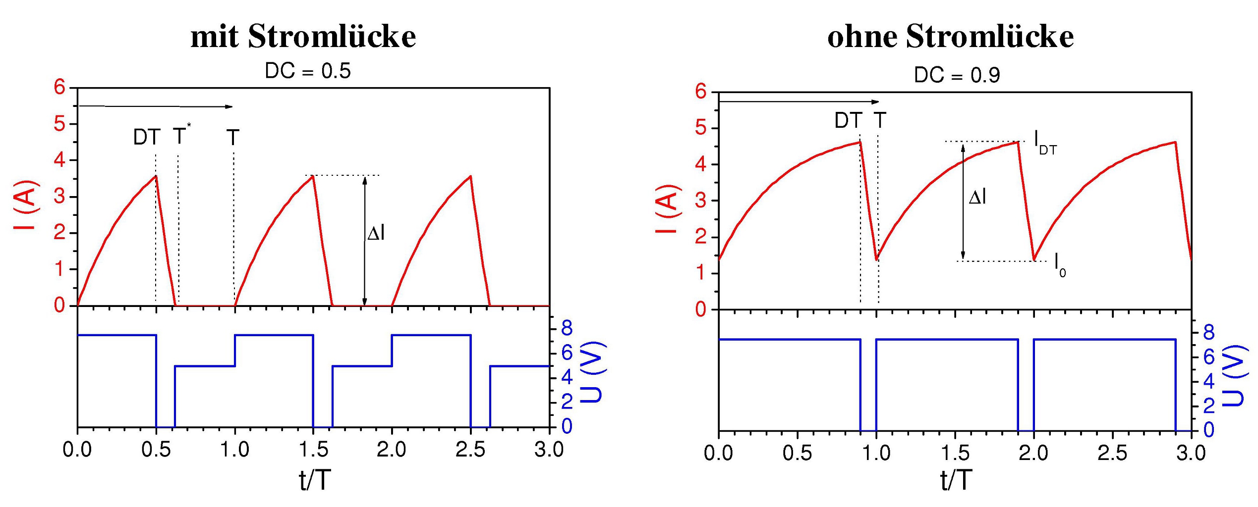
there is a very detailed article about voltage and current in a PWM contolled BLDC.

pwm-elektromotor-fig1.jpg


pwm-elektromotor-fig3-wp.jpg


To be honest, I don't understand everything, but the fog has cleared a little, now.

regards
stanceocke
 
To move forward with development, I found the need to use UART for debug and disconnect the LCD. Since LCD send values for some variables, I decided to move forward implementing EEPROM variables storage. And finally I saw myself doing a lot of code that is a mess because of all the compartmentalization I created before, so I am now simplifying:
- ebike_app.c: throttle_pas_torque_sensor_controller; communications_controller; etc
- motor.c: all low level/fast loop and high level/slow loop

That way will simplify coding but at same time each of that 2 files will get bigger.
 
Sorry, the pictures are just linked from the original source.

Alan B said:
measured inductance (star configuration): 133.6 uH
total system 'resistance' (star configuration): 93.3 mOhm
This makes Tau = L/R = 1.4 mS (electrical time constant of the motor)

Our PWM period is 64µs. Can you draw a sketch for Voltage and Current for a duty cycle of 0.5 e.g, please?

regards
stancecoke
 
Not a very interesting graph.

If you have a motor time constant of 1.4 mS and PWM of 64 uS then you will have DC current with a tiny ripple on it. The motor inductance will filter the PWM into DC current. The voltage will be rail to rail DC of course with the PWM duty cycle. This is what we should have. If in a sinewave commutation mode the DC will convert to roughly a sinewave with the same little 64 uS ripple on it.
 
casainho said:
... I decided to move forward implementing EEPROM variables storage.
... so I am now simplifying:
- ebike_app.c: throttle_pas_torque_sensor_controller; communications_controller; etc
- motor.c: all low level/fast loop and high level/slow loop
Wow, this was much work, I believe, I had to look around in the code for a while, to find what's happening where... :D
It's really good to have the user set parameters in the EEPROM. Are you planning to add an function that can modify the parameters over UART with a PC-Tool? Then you could modify much more things than you can set with the Display....

Alan B said:
Not a very interesting graph.
I was interested in this not interesting thing and made some measurements with the oszi :wink:

Voltage and Current within a PWM cycle.PNG

regards
stancecoke
 
EEPROM code is now finished :)

On ebike_app, when we receive a full package from the LCD, we call eeprom_write_if_values_changed ();:


Then, that code will verify if the content of variables received from the LCD differ from the values stored in EEPROM and if so, will write all the values to EEPROM:


Also after programming the firmware, we verify if EEPROM first address is different from our "key" value (it is 0 after erasing) and if so, we write the default values, so user don't need an LCD to have a full working system (but need one to change that values)

 
stancecoke said:
It's really good to have the user set parameters in the EEPROM. Are you planning to add an function that can modify the parameters over UART with a PC-Tool? Then you could modify much more things than you can set with the Display....
I am not planning (at least for now) because I would like to focus on getting the firmware doing what original firmware does (which is a lot), and we are not there yet, for instance, there are a other options that LCD configure that I didn't code yet for lack of time/priority/need.
But my mainly stress is memory size, the code is now with ~23kbytes of total possible 32kbytes!! :-(

stancecoke said:
I was interested in this not interesting thing and made some measurements with the oszi :wink:
Thanks for sharing!
 
casainho said:
I would like to focus on getting the firmware doing what original firmware does
Hm, that's nice to have, but no one will use our firmware if there are no additional features against the Kunteng firmware. But no problem, we can use the Java Tool for the parameters of the additional functions meanwhile.

casainho said:
there are a other options that LCD configure that I didn't code yet for lack of time/priority/need.
I agree, it's much more important to implement the PAS-Modes in the master branch. The throttle mode is completely stupid. If I want to take a motorcycle ride, I'll take my BMW!

regards
stancecoke
 
Back
Top