KT motor controllers -- Flexible OpenSource firmware for BMSBattery S/Kunteng KT motor controllers (0.25kW up to 5kW)

stancecoke said:
casainho said:
I would like to focus on getting the firmware doing what original firmware does
Hm, that's nice to have, but no one will use our firmware if there are no additional features against the Kunteng firmware. But no problem, we ca use the Java Tool for the parameters of the additional functions meanwhile.
I think the additional features may not be "big ones" but things like having cruise control the way it is now, that I prefer and not like original mode. The cruise control now is like implemented on old KUxxx controllers that BMSBattery sells since always -- this is flexibility and like personalization :)
Also, I hope that with our firmware, we can document a way for users be sure that they are getting best energy efficiency, by tunning the angle that I think can be different from motor to motor and that can't be done with original firmware.
Well, but in the end we can see what memory is available and decide.

stancecoke said:
I agree, it's much more important to implement the PAS-Modes in the master branch. The throttle mode is completely stupid. If I want to take a motorcycle ride, I'll take my BMW!
Sorry but I want to put my time in improving motor code. For instance, I don't like the way we adjust now the angle -- I think having it in terms of angle value/time may be better than actual phase B current value -- I hope to be able to improve motor efficiency and having a clear process to do it.
But I will receive a torque sensor and so I will also want to make it working :)
 
so it seems, that we have quite contrary opinions of what is important :D

regards
stancecoke
 
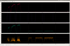
Screenshot from 2017-11-08 17-44-33.pngSo I was looking at real time log of PWM duty_cycle value to see how it changes when I brake the motor (but with brakes disable from the controller) and the motor_max_current is hit.

With motor_max_current = 10 (represents ~5Amps) setup on the current controller for this test, I did log the following variables:
- motor_speed_erps: motor speed in ERPS
- duty_cycle_target: is the value set by throttle that is the value we want to apply, but ramp up/down controller and current controller will setup a different PWM duty_cycle if needed
- duty_cycle: this is the real PWM duty_cycle applied to motor
- adc_motor_total_current: each 1 unit represents ~0.5A

See the screenshot (click on the screenshot link to get full size):

View attachment 1
1. From 0 to about 2000 I were testing by accelerating from 0 to max throttle, without braking the motor -- see the motor speed and also the 2 duty_cycle values.
2. After 2000, I started to brake the motor up to 4600 and I did 3 levels of braking as seen on the motor speed. See that although throttle were at max value (duty_cycle_target), the real duty_cycle value were lowered by the current controller -- see that it almost never passes the motor_max_current of 10, as imposed by the current controller.

What about trying to start the motor while it is stalled with full brakes?? -- see the screenshot:


1. From 0 to about 1400 I were testing by accelerating from 0 to max throttle, without braking the motor -- see the motor speed and also the 2 duty_cycle values.
2. After 1400, I stopped the motor, stalled it with the brakes and tried to put throttle to max value. As you can see, the duty_cycle always do a ramp up/down, that is the task of ramp controller. But also tops constant at adc_motor_total_current = 10 (which is 5A), that is the task of current controller.

So, seems to me that motor max current controller is working well!! Although the current value could be filtered a bit and maybe if could make some cleaner results/lines.

And now looking at what is the "resistance" (don't know if is correct to call it resistance). R = U / I; U = 30V * duty_cycle 15.6 = 4.68V; R = 4.68 / 5 = 0.93 ohms. Don't know if this is correct.

And as I did show before, the ramp and current controllers are implemented on the firmware as this:
 
casainho said:
So, seems to me that motor max current controller is working well!! Although the current value could be filtered a bit and maybe if could make some cleaner results/lines.
I let the motor stalled with the brakes about 2 minutes with the 5 amps and I put my hand on the S12S metal enclosure and I could feel the temperature rise... no mosfets did burn during this 2 minutes and the temperature maybe was at about 40º (??).

Bug!! Seems that at some motor position, the current control fails -- maybe it is at hall sensors commutation??
The duty_cycle ramps up!! and just stops when my power supply resets on it's current limit... I wonder what happens with a battery with big amps capacity ;)

 
stancecoke said:
so it seems, that we have quite contrary opinions of what is important :D
What contrary opinions? about PAS/torque sensor? about which features? about the software Java Tool?
 
casainho said:
What contrary opinions? about PAS/torque sensor? about which features? about the software Java Tool?
About what to implement next in the master branch. I think, the motor code is OK (even without 6 step), the efficiency is as good as a much more expensive Lishui Controller. Of course we have to fix the thing with the burning mosfets, but you got a first trace, what's going wrong now. Thumb up!
Throttle or even autocruise are not legal to use in Germany, so a solution with PAS is very important for me (and already implemented in the forked branch)...

I wonder what may cause the fault with the high current at the blocked wheel. Why should a certain hall-sensor case / rotor position should have any influence, while sending the values over UART works all the time obviously?!
And motor current is not proportional to the PWM-Value?! Just a very short peak of high current?! Could it be a matter of delay-times at ADC again, as the ADC values for current are not correct oviously, when the duty cycle ramps up...


regards
stancecoke
 
The only time that current is proportional to PWM duty cycle is when the rotor is locked (making back EMF zero). If the wheel is turning the back EMF cancels part of the supply voltage and only the remainder creates current:

current = (battery voltage * duty cycle - back EMF) / resistance

Note that if there is an error in the hall signals the wrong coils can be energized which can cause the back EMF to add to the battery voltage (instead of opposing it) and create current surges:

current = (battery voltage * duty cycle + back EMF) / resistance (the plus value is a big problem if there is much back EMF, eg at speed)

Getting the rotor position wrong can create tremendous current surges!
 
Alan B said:
The only time that current is proportional to PWM duty cycle is when the rotor is locked
I don't want to count beans, but current is proportional to the duty cycle as long as you keep the motor speed constant :wink:

regards
stancecoke
 
Folks generally mean y = m*x + b where b == 0 when they say proportional. A quick search shows most definitions are y = m*x, which is more precisely called directly proportional.

If b is nonzero then it is usually said to be linear rather than proportional.

At any rate, good progress on your project. One advantage of using existing low cost hardware. The downside is only 32K in the chip will limit what can be done and chew up effort trying to keep things fitting.

I've been doing a little work on my similar project with the ATmega64M1, but the disadvantage is that I haven't built hardware yet (and it is not so cheap to buy the demo boards, the chips are cheap however), so it is more theoretical at this point. I haven't compared the chips in detail, that might be interesting to do, but I suspect they're similar in many respects. Both are using the same compiler core (GCC), and are similar in speed (16 vs 20 mips). The memory size of the ATmega64M1 is apparently double of the STM8 chips on these boards, if I understand the remarks I've seen here. They both have pin change interrupts. The ATmegaxxM1 family has a very sophisticated six output Power Stage Controller for generating three phase PWM, I'm not sure what the ST8 has there. The STM8 ADCs seem to be 12 bit whereas the AVR's are 10. The AVR has a DAC output and comparator that can trip off the PWM outputs in hardware for very fast response overcurrent shutdown that is not dependent on the CPU's response time.
 
Alan B said:
At any rate, good progress on your project. One advantage of using existing low cost hardware. The downside is only 32K in the chip will limit what can be done and chew up effort trying to keep things fitting.
Yes but I also see one advantage, less possibilities of many features which should make the project small and so more probability to finish it!! :)

Alan B said:
I've been doing a little work on my similar project with the ATmega64M1, but the disadvantage is that I haven't built hardware yet (and it is not so cheap to buy the demo boards, the chips are cheap however), so it is more theoretical at this point.
You should join this project (didn't you already? ;) ). Count the number of users on this forum that made their own hardware/motor controllers and see which of them is available to buy online and possible to ship to any country in the world - and with accessible price.

Alan B said:
I haven't compared the chips in detail, that might be interesting to do, but I suspect they're similar in many respects. Both are using the same compiler core (GCC), and are similar in speed (16 vs 20 mips). The memory size of the ATmega64M1 is apparently double of the STM8 chips on these boards, if I understand the remarks I've seen here. They both have pin change interrupts. The ATmegaxxM1 family has a very sophisticated six output Power Stage Controller for generating three phase PWM, I'm not sure what the ST8 has there. The STM8 ADCs seem to be 12 bit whereas the AVR's are 10. The AVR has a DAC output and comparator that can trip off the PWM outputs in hardware for very fast response overcurrent shutdown that is not dependent on the CPU's response time.
- Forget about AVR - I had work with them in the past and I liked a lot the support of GCC and the datasheets and community, but they lack a cheap and OpenSource tool for debug like we have on STM32/STM8!! We use SDCC for STM8, no GCC available.
- Go to Ebay and find the cheaper Arduino board: it is STM8 and STM32. From china we see a lot of devices with STM32, see hoverboards and many other motor controllers!!
- STM8 have 6 PWM channels, complementary and we are using them. STM8/STM32 have TIMER 1 with specific hardware for motor control, but STM32 is more powerful TIMER1 for motor control.
- STM8 ADCs are also 10 bits.
- STM8/STM32 also have a digital pin for "break" on TIMER1, that can disable directly the duty_cycle. But on sinewave, that is not ok as it is the same as change the PWM/sinewave shape, so not needed.
- Are you looking to more flash memory on STM8 on this Kunteng motor controllers??
-- original is STM8S105C6T6, 16MHz, 32kbytes flash memory
-- pin compatible: STM8S208CB, 24MHz, 128kbytes flash memory -- so if you are looking to build your hardware, you should be able to solder, so you can swap the original STM8 to this new one :)
See here: https://opensourceebikefirmware.bitbucket.io/Motor_control--STM8S105_Alternatives.html

Debug session we have on STM8/STM32/ARM, we can stop the firmware execution, see variables, change their value on the fly, etc, etc -- you need to zoom out in your browser: https://opensourceebikefirmware.bitbucket.io/Development_tools--Linux--Step-by-step_tutorial_development_tools--(optional)_Tools_do_flash_and_debug_the_firmware.html

30-9.png
 
Alan B said:
current = (battery voltage * duty cycle - back EMF) / resistance
I think it is good idea to limit the duty cylcle according to this. Maybe, we can allow 10% more current as defined as maximum current in the code. Then we are no longer depending on a correct ADC value for the current to limit it, and it is very simple to implement into the code in the fast loop.
Code:
dutycycle max = 255*(current_max * 1.1 * resistance + erps/motor_velocity_constant)/battery voltage
We only need to know two motor specific constants: the motor velocity constant kv' [erps/V] and the resistance [Ohm].

regards
stancecoke
 
I took another screenshot, this time showing also a variable "commutation_number" that increments/decrements sequential and represents the hall sensors "sector", 1 up to 6.

On this test I were holding the Q85 motor with my hand and force it to run backwards (yes, with 5 amps I can hold it and even force to run backwards) or run it forward while still holding it:


From 1500 up to 2000, I were forcing it to go backwards and the commutation_number went from like 6 -> 5 -> 4, etc. Seems that when running backwards, it always works as expected!! But when I try runs forwards, I can hear a more noise on the motor and see the current control failing -- we can see on the screenshot, comparing the orange line /duty_cycle that is 40 when things works ok but goes higher when don't even if the readed current value seems to be lower.
 
stancecoke said:
casainho said:
What contrary opinions? about PAS/torque sensor? about which features? about the software Java Tool?
About what to implement next in the master branch. I think, the motor code is OK (even without 6 step), the efficiency is as good as a much more expensive Lishui Controller. Of course we have to fix the thing with the burning mosfets, but you got a first trace, what's going wrong now. Thumb up!
Throttle or even autocruise are not legal to use in Germany, so a solution with PAS is very important for me (and already implemented in the forked branch)...
Ok I see. Ok I agree that after having motor code not blowing the mosfets, to put PAS and Torque Sensor working and I will look at your code. For what I saw from your code and explanations, for torque sensor we need to also put PAS working so I will be doing the 2 things at the same time.

I should receive in 2 weeks the torque sensor and more S06S controllers. But my motors are bad, I can't trust them no more, I now understand I did heat them a lot and they now make strange noises. I will receive at the same time one Q11 direct drive but will take maybe another 2 weeks to get it on the bicycle... and it is a different motor, always makes regen and can't be started while already running as theses geared motors I am running so I think it will take some time more to get all this working........

I don't know if I should invest again on geared motors, I like them because they are small, more light and cheaper. I have some family small ebikes, seems direct drive motors can't work there. But the issue is that I wasn't using the temperature sensor of this motors, I really need to take care of them -- something to implement also on the firmware.
My Q100 motor is a 36V motor but I did run at 48V. My Q85 motor is a 24V motor but I did run a few days ago at 48V and I could feel it going slower and slower and making more and more noise... and this motors are high rpm for small wheel but I run them in 26'' wheels, meaning they should heat a lot, other than me overvoltaging them.
 
Ok I think I have some ideas:


On that image, the motor was oscillating between commutation_number 5 and 6, even if I was blocking with my hand. When oscillating, we can see the current readings seems lower and the voltage keeps increasing.. and at some times, when it is at a steady commutation_number, all works good.

And I need to see if the read current is the real current my power supply measures, because at 4000 I think my power supply shuts down quickly/or reduces the supply voltage due to high current (more than 10A) but the read current by ADC is lower than 5A....
 
casainho said:
On that image, the motor was oscillating between commutation_number 5 and 6, even if I was blocking with my hand. When oscillating, we can see the current readings seems lower and the voltage keeps increasing.. and at some times, when it is at a steady commutation_number, all works good.

And I need to see if the read current is the real current my power supply measures, because at 4000 I think my power supply shuts down quickly/or reduces the supply voltage due to high current (more than 10A) but the read current by ADC is lower than 5A....
I verified that on fast oscillating between commutation_number, the value of current ADC is lower as also what I see on my power supply, so I think current readings are ok.

What is clear is that current on that fast oscillating between commutation_number (that happens when the motor is blocked on a position that is near the commutation) is lower and at stable commutation_number is higher. Seems to me that current controller is working well, ramping up the duty_cycle when it measures a current under the limit. And on transitions the duty_cycle increases but as soon passes the transition and is stable, the duty_cycle value is now to high and hits the current limit of my power supply (on battery may burn the mosfets).

So the question is why this happens, why this works this why on transitions??
 
If the motor is not moving then the oscillation is magnetic in nature and may indicate the motor has design issues. The hall sensors generally have magnetic hysteresis to avoid this, but the hall sensors must be not seeing just the permanent rotor magnets, but also some noise from the stator fields. Oscillations are often damaging if they continue, and it will prevent the locked rotor code from tripping off.
 
Alan B said:
If the motor is not moving then the oscillation is magnetic in nature and may indicate the motor has design issues. The hall sensors generally have magnetic hysteresis to avoid this, but the hall sensors must be not seeing just the permanent rotor magnets, but also some noise from the stator fields. Oscillations are often damaging if they continue, and it will prevent the locked rotor code from tripping off.
Well, I now can reproduce the issue very well. I just need to be blocking the motor and slightly oscillating with my hand on the position that happens a transition... the faster I do it, the more I can see the duty_cycle increase up to a value were my power supply disables the power:


Maybe I am doing something wrong on the code... maybe it is because of disabling the PWM from phase to phase, as the commutation happens??

This is the code that happens on the commutation, let's say from 5 <-> 6:

Code:
      case 6:
      ui8_commutation_number = 5;

      pwm_phase_a_enable_low ();
      pwm_phase_b_enable_pwm ();
      pwm_phase_c_disable ();
      break;

      case 2:
      ui8_commutation_number = 6;
      
      pwm_phase_a_disable ();
      pwm_phase_b_enable_pwm ();
      pwm_phase_c_enable_low ();
      break;
 
I got it!! well, more or less :)

As stancecoke is being telling, for his motor, starting with sinewave no interpolation works well, he don't feel the need for block commutation/6steps. And I went and tried that and the result is perfect :) -- the only thing is missing for me is that I can't after jump to interpolation, but maybe is something I need to work on. OR, seems it is something about the phases changing to/from PWM or disable...

Alan B said:
Do you disable / enable things in a safe order? Looks like the order of operations there isn't optimized.

How long do those function calls take?
Don't know what would be a safe order... can you help?

Don't know how much time takes, but maybe no more than 64us * 2.
 
When doing realtime software it is important to understand how long various operations take. On these small processors some things are surprisingly slow. Function calls cause the register set to be invalidated and local variables and function arguments can be surprisingly inefficient. Calls and returns often do a bunch of stack related operations, especially if any debugging is turned on there may be a lot of extra code in there.

I haven't looked in detail at the hardware here, but in general you might want to do all the disabling of outputs before enabling anything, or you might want to disable all the outputs first then set up the two that are needed now. The hardware probably protects things but you don't want to depend on that. In my case with the Power Stage Controller there is a synchronization layer in the hardware, so you can set up all the changes, and they will all take effect later at exactly the proper time.

How are your ADC reads synchronized? I'm planning to take them right at the center of the PWM pulse using the hardware trigger in the Power Stage Controller (or where the pulse would be if it is off), so as far from the edges where things change and generate noise as possible. I'll rotate the ADC channel being read so the current is read most often, and other channels less often as commensurate with the requirements. Perhaps a commutation event should set a flag to discard the next ADC event because it may be noisy if it occurs too close to the asynchronous commutation.

Each time the software commutates the motor there are disruptive transients as the stored magnetic energy is dissipated from the previous coil configuration. The current will abruptly change during the transient, then drop and rise slower as it charges the next coil sets, so you may not want to respond to the undercurrent readings till the transient is gone. You probably always want to respond to the overcurrents, at modest levels reducing the PWM and at significant overcurrents tripping the outputs completely off (maybe there's a short or a bad hall sensor or the hall order is wrong or an FET has shorted).
 
Alan B said:
How are your ADC reads synchronized? I'm planning to take them right at the center of the PWM pulse using the hardware trigger in the Power Stage Controller (or where the pulse would be if it is off), so as far from the edges where things change and generate noise as possible. I'll rotate the ADC channel being read so the current is read most often, and other channels less often as commensurate with the requirements. Perhaps a commutation event should set a flag to discard the next ADC event because it may be noisy if it occurs too close to the asynchronous commutation.
On STM8 is possible to read at middle also using the interrupt but I found it very slow for the current code that is almost the 64us!! I just trigger ADC reading at start of PWM cycle and STM8 reads all the channels in sequence, before the 64us. For now, this seems to work quite well.
 
Alan B said:
Where are the PWM edges compared to the PWM cycle? You don't want to read any critical ADC values near any switching.
I think the edges are at begin and end of PWM cycle. Or maybe not, I will not use energy until I found that it can be an issue. I saw VESC code (STM32 32 bits 168MHZ FPU) and does a lot of math to do that, because duty_cycle value will change the edges... and it is not possible to do the STM8 8 bits 16MHZ no FPU.
 
It is hard to write good code if the hardware is not understood. At least one of the edges needs to move when pulse width changes. On the ATmega64M1 I've been studying the PSC PWM hardware, so I can choose the mode of PWM and know what the timing is and where the edges are. In that case I'm choosing centered PWM so the edges are away from the center of the PWM cycle except when PWM values are very small. The ADC is triggered in hardware and the register that controls it can easily be adjusted to acquire the channels away from the noisy switching edges. The interrupt we need is after the ADC conversion in order to process the resulting value. An interrupt should only take a few clock cycles, just a few more than a no argument function call.
 
casainho said:
This is the code that happens on the commutation, let's say from 5 <-> 6:

Code:
      case 6:
      ui8_commutation_number = 5;

      pwm_phase_a_enable_low ();
      pwm_phase_b_enable_pwm ();
      pwm_phase_c_disable ();
      break;

      case 2:
      ui8_commutation_number = 6;
      
      pwm_phase_a_disable ();
      pwm_phase_b_enable_pwm ();
      pwm_phase_c_enable_low ();
      break;
Changed from that code to this one in the hope it could be fast and solve the issue, but didn't. I think it did improve a small bit but still having the issue. So net step will be going with sinewave without interpolation as I had before working (but had the issue that I could not commutate to interpolation mode).

Code:
      case 6:
      ui8_commutation_number = 5;

      // disable PWM channel pins
      TIM1->CCER2 &= (uint8_t)(~( TIM1_CCER2_CC3E | TIM1_CCER2_CC3NE));
      // PWM channel N as IO pin and output low (enable power mosfet)
      PMW_PHASE_A_LOW__PORT->ODR &= (uint8_t)~PMW_PHASE_A_LOW__PIN;
      PMW_PHASE_A_LOW__PORT->DDR |= (uint8_t)PMW_PHASE_A_LOW__PIN;

      // PWM channel N as IO pin and output high (disable power mosfet)
      PMW_PHASE_B_LOW__PORT->ODR |= (uint8_t)PMW_PHASE_B_LOW__PIN;
      PMW_PHASE_B_LOW__PORT->DDR |= (uint8_t)PMW_PHASE_B_LOW__PIN;
      // disable PWM n channel
      TIM1->CCER1 &= (uint8_t)(~(TIM1_CCER1_CC2NE));
      // enable PWM p channel
      TIM1->CCER1 |= (uint8_t)(TIM1_CCER1_CC2E);

      // PWM channel N as IO pin and output high (disable power mosfet)
      PMW_PHASE_C_LOW__PORT->ODR |= (uint8_t)PMW_PHASE_C_LOW__PIN;
      PMW_PHASE_C_LOW__PORT->DDR |= (uint8_t)PMW_PHASE_C_LOW__PIN;
      // disable PWM channel pins
      TIM1->CCER1 &= (uint8_t)(~( TIM1_CCER1_CC1E | TIM1_CCER1_CC1NE));
      break;

      case 2:
      ui8_commutation_number = 6;
      
      // PWM channel N as IO pin and output high (disable power mosfet)
      PMW_PHASE_A_LOW__PORT->ODR |= (uint8_t)PMW_PHASE_A_LOW__PIN;
      PMW_PHASE_A_LOW__PORT->DDR |= (uint8_t)PMW_PHASE_A_LOW__PIN;
      // disable PWM channel pins
      TIM1->CCER2 &= (uint8_t)(~( TIM1_CCER2_CC3E | TIM1_CCER2_CC3NE));

      // PWM channel N as IO pin and output high (disable power mosfet)
      PMW_PHASE_B_LOW__PORT->ODR |= (uint8_t)PMW_PHASE_B_LOW__PIN;
      PMW_PHASE_B_LOW__PORT->DDR |= (uint8_t)PMW_PHASE_B_LOW__PIN;
      // disable PWM n channel
      TIM1->CCER1 &= (uint8_t)(~(TIM1_CCER1_CC2NE));
      // enable PWM p channel
      TIM1->CCER1 |= (uint8_t)(TIM1_CCER1_CC2E);

      // disable PWM channel pins
      TIM1->CCER1 &= (uint8_t)(~( TIM1_CCER1_CC1E | TIM1_CCER1_CC1NE));
      // PWM channel N as IO pin and output low (enable power mosfet)
      PMW_PHASE_C_LOW__PORT->ODR &= (uint8_t)~PMW_PHASE_C_LOW__PIN;
      PMW_PHASE_C_LOW__PORT->DDR |= (uint8_t)PMW_PHASE_C_LOW__PIN;
      break;
 
Back
Top